First
I am not an electrical engineer. I am however an electronics
hobbyist and can read a simple schematic and I understand how the basic
electronic components work.
Second
I did not come up with some of this information on my own. I
spent a lot of time online researching. I found a few web articles and
some YouTube videos that guided me, however each of them only provided
a small piece of what I am trying to put together as a more complete
guide.
Third I
used my basic electronics knowledge, the knowledge I gained from the
above mentioned sources and experimentation to come up with all the
information I am about to present. The final result and ultimately what
I am trying to provide is a one stop location with as much information
as possible so others can read it and make informed decisions on what
will work best for their application.
Forth WARNING AC current can be lethal when used incorrectly. The power going into the SCR controller is AC and the power coming out of an SCR controller is AC. All wiring should be done by a qualified professional. Use the information below at your own risk.
Tools Required:
Other than a soldering iron for doing electrical connections, and basic
fabrication tools to mount a motor in its new home and be able connect
it to whatever it will be driving there is not a lot needed to install
a treadmill motor. However there are two tools that while not required
make the install much easier and precise. The first is a
multimeter AKA volt ohm meter. This basic electronic tester is
used for all kinds of things but in this case measuring continuity and
resistance is what I used it for. I will explain further down in
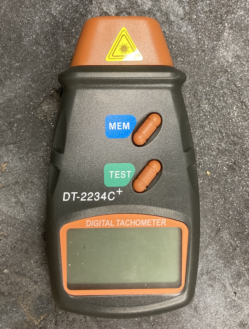
“setting up the potentiometer speed control” The second tool I found
extremely useful was a handheld RPM meter. It uses inferred and
silver tape placed on the rotating part to measure RPMS. Not only
was this helpful in testing all the different parts I had but also for
setting the tools up in the correct operating ranges.
What started this project:
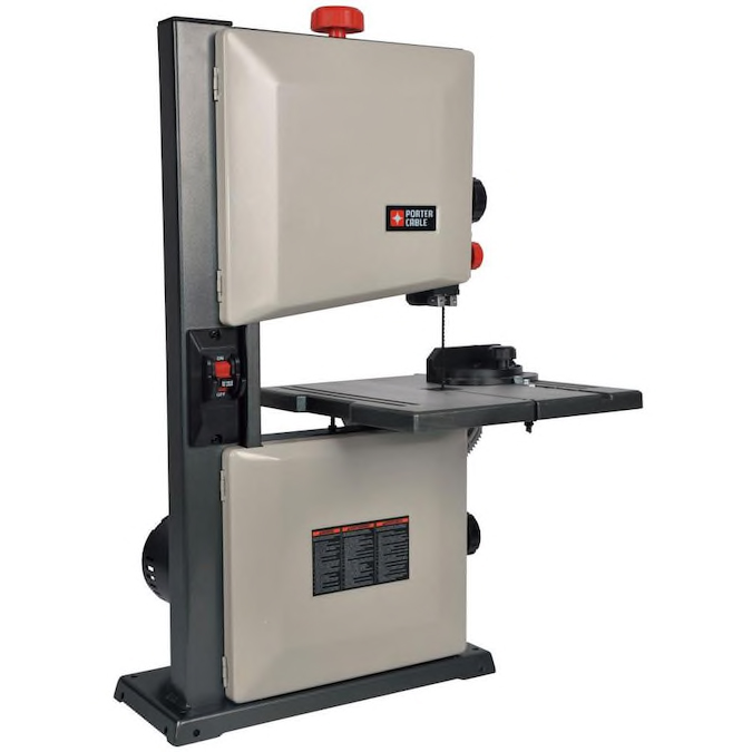
Couple years back I purchased a band saw It is a bench top unit and is
the perfect size for smaller, more detailed projects. It was
designed for wood with a blade speed of 2300 FPM BUT they make metal
cutting blades for it. I purchased a couple of the metal cutting
blades and have used them on Aluminum and copper with out any issues
but its way to fast to cut steel. If you try to cut steel with a
metal cutting blade at the full 2300 FPM the blade works amazingly well
for about a minute but after that the blade fails and will no longer
cut anything.
9" band saw from Lowes
The obvious solution is to slow down the speed of the blade and my
original plan was to use pulleys and belts to reduce speed but the band
saw is so small that consequently there is not a lot of room to add
parts, so I was not able to make the modifications I wanted
to.
I
then tried a router speed controller hoping it would work and it did
slow down the motor some but not enough and it also reduced the torque
of the motor. After doing further research I also learned that
those speed controllers are hard on the motors and will shorten their
life. With two failed attempts at slowing down the blade speed I
was about to give up but then my brother told me about the DC motors in
treadmills. They are high HP/torque and by changing the voltage
you can change RPM but not loose torque.
I began researching how to make this happen and found lots of
information on line, some of it good, some of it not so good and as I
said above none of it was “complete”.
My initial research said “get a treadmill remove the motor control
board and the motor, attach a potentiometer (pot) to the control board
at the H, W, and L terminals and you are good to go.” However it
was not even close to that simple. The first three treadmills I
took apart had boards that were way more complicated which meant they
did not have the H, W, and L terminals. I have now taken apart a total
of five treadmills. Out of those five only one treadmill had the
correct board, but before I got the correct control board I searched
for other options.
Speed controllers:
To adjust speed, a lot of people using treadmill motors on shop tools
are using a board called an “MC-60 speed controller”. A few
treadmills come with these boards but if you are not lucky enough to
have one come with the treadmill you are using for parts, they are
available on eBay, and cost between $60-$100. I was trying to
keep this project budget friendly and continued researching other speed
control options and found a couple YouTube videos on treadmill motors
where they were using a different setup to control speed. Their
solution was to get an AC SCR voltage controller for about $15.00, wire
a bridge rectifier to it and use this combination of parts to control
the speed of the motors. An MC type board and an SCR voltage
controllere are the two most commonly used ways to power a DC motor
from a 110 AC outlet.
An SCR controller modifies AC voltage and then you must use a bridge
rectifier to convert that voltage to DC. The MC boards use PWM,
which stands for “pulse width modulation” These boards starts by
converting the AC to DC and then pulses the DC current to reduce
voltage.
While both the SCR and PMW type controls are effective at providing
motor speed control there are some advantages and disadvantages of
each. An SCR controller is significantly less expensive, has
fewer parts so fewer parts to fail, is more robust, and is able to
handle higher current motors, but it makes a buzz when running, and is
harder on the brushes and commutator (the contact the brushes ride on).
However both of these negatives can be mitigated as I will explain
further below. PWM controllers such as the MC-60 are more expensive,
wired from the factory with “soft start” (soft start can be eliminated
but requires more components) have lower current limits, and are not as
robust as their SCR counterparts, but they run silently and the motor
runs “better” with a longer brush and commutator life.
So the question is, which is the correct choice, the SCR controllers or
the PWM controller and the answer due to their advantages
and draw backs is it will depend on your application and needs.
PWM
(MC-XX)
SCR
Knob Speed Control
X
X
More Durable
X
Higher Amperage
X
Better for Motor life
X
Turn it on at set speed
X*
X
Less expensive
X
Set Max Speed
X
Quieter
X
X**
* Requires extra parts to eliminate soft start ** Noise and brush life issues can be reduced with extra parts.
SCR voltage controllers:
First you need to know that you can not hook an SCR voltage controller
directly up to a treadmill motor. A treadmill motor runs on DC
and the output of an SCR controller is AC. This is easily fixed
with a high amperage bridge rectifier. It will convert the AC to
DC, more on that later.
Second not all SCR controllers are created equally. They come in
many different wattages but I wanted one that would put out more
wattage than I needed so that it would last longer. The highest
one I could find was 10,000W peak with 5000W sustained. When you
calculate it out 5000W at 110 V works out to be about 45 amps and most
of these motors are 15-30 amps so the 10,000W controller is the perfect
size. There are at least three different budget friendly versions
available on eBay and Amazon ranging in price from $10-$25. I
have several projects that will all need a controller, so I purchase
one of each that way I could compare them.
I set up each of the three controllers and compared their brush
spark. What I mean by brush spark is, on one of my motors I could
easily see through the vent holes to where the brushes make contact to
the commutator. At higher speeds >3000 RPMs this contact point
would spark. This sparking action shortens brush, and commutator
life so observing sparking is a visual measurement of the quality of
the SCR controller, and eliminating that spark is a good indication of
improving SCR function.
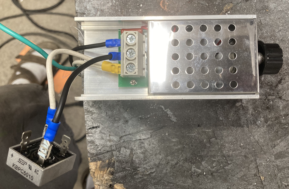
The first SCR controller is the most inexpensive and the old saying is
true, you get what you pay for. This unit is noisier than the
other two, makes the motor run a little nosier and was the worst when
it comes to brush spark. Also the knob on the controller had to be
turned quite a bit before the motor would start. I knew from my
research that having to turn the knob quite a bit just to start the
motor was going be an issue and I will address the solution in the
section “Setting up the potentiometer for speed control.”
Depending on which motor I was using the lowest RPMS I could get with
this controller were between 450 and 500 RPMs
SCR Controller 1
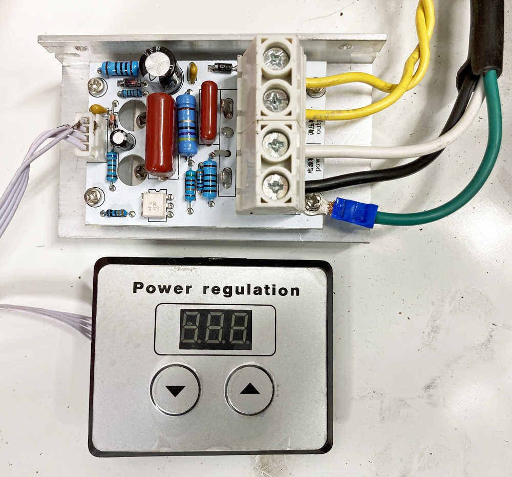
The
second controller was only slightly more expensive than the first one
and came with a digital display. It was slightly less noisy than
the least expensive controller and the sparking at higher RPMs was
almost the same as controller 1, but maybe marginally less. One
advantage of this unit is that it started the motors at a lower RPM
range 300-400 RPMs however you had to start at a minimum setting on the
display of 5 to get the motor to turn on. Also one thing that
could be a benefit or a problem depending on how fine a speed control
you needed for your application is that increasing the display by 1
increased the RPMs by roughly 100 RPMs. It has the advantage of
knowing how fast each setting will be without having to measure but the
disadvantage of not having any speeds in between each 100 RPM increase.
UPDATE 02/10/2021 I do not recommend this controller!!
I had been using controller number 3 on my band saw and was very happy
with it. It was working well, however I needed to use that controller
for another project so I decided to mount controller 2 on the band
saw. I figured it would work well for set speeds depending on
what I was cutting. In other words I could make a chart that told
me what number to put it on based on what material I was cutting.
I spent an afternoon making an enclosure for it, getting it mounted up
and was happy with the install. That was until a couple days
later when I went to use the machine. When I pushed a piece of
aluminum into the blade rather than slowing only marginally like it
hade with controller 3 it bogged down a lot, at least 1/2 to 1/4 the
speed it had started at. I had to ramp the starting speed way up
just to get a decent cutting speed once material came in contact with
the blade. I am not sure what makes this unit different
electronically but it obviously does not work well in systems where the
motor is under a load. I replaced it with controller 1 and have
been happily using my band saw ever since.
SCR Controller 2
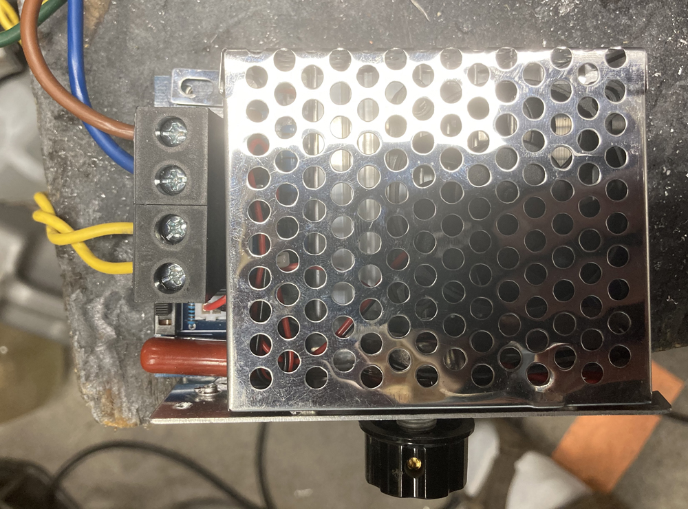
The
third controller was by far the best of the three. It was twice
as expensive as the cheapest one but came with an internal cooling fan,
is completely enclosed, and of the three was the quietest and produced
the least spark inside the motor. This is the SCR controller I
would recommend unless you need the lower RPMs provided by controller
two.
SCR Controller 3
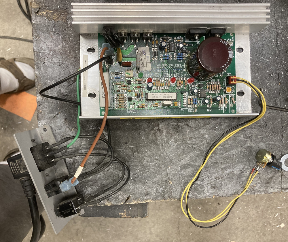
PWM controllers:
As I said above one of the treadmills I parted out came with the
correct board to use as a controller. It had an MC-2000, which
has almost everything you need to use it to control motor speed.
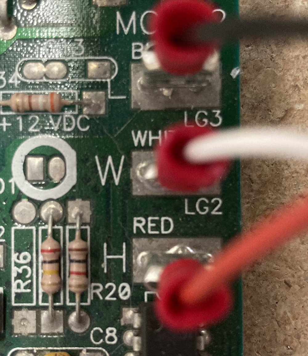
There
are three terminals on the board marked L, W, and H and these terminals
are what you use to control speed. All you need to do is get a
variable resister, or potentiometer and connect its three terminals to
the H, W, and L inputs.
When
wiring one up the middle terminal on the potentiometer goes to the W
and for the outside terminals one goes to H and one goes to L.
Therese terminals can be interchanged depending on which way you want
the nob to work. Attaching the H to the left terminal will give
you a clockwise knob rotation to increase speed. Connecting the H
to the right terminal will give you a counter clockwise knob rotation
to increase speed. I tried several different potentiometer sizes
from 10KΩ all the way to 500KΩ and they all seamed to work about the
same. This controller runs quiet, there is little to no sparking
inside the motor, and is an outstanding option except for the soft
start.
Soft
start means the circuit will not restart at the last speed it was set
at. In other words if using the machine at 600 RPMS and you then shut
the system off when you turn the system back on the motor will
not turn on. You need to turn the potentiometer all the way down
to the slowest speed and then when you go back up it will start slow
and then increase as the knob is turned; great for a treadmill, but not
for a shop tool. This can be fixed by putting a normally closed
push button switch in line between the potentiometer and the H terminal
to disable soft start. To use it, with the power off, push the
button, effectively disconnecting H from the potentiometer, turn
the main power switch on and then release the button which will
reconnect h to the potentiometer. This will cause the motor to
spin up to the speed corresponding to where the potentiometer is
set. Others have used delayed relay timers in place of the switch
but to me this is a more expense option with more to go wrong.
IMHO the two button system is completely effective and the simpler way
to go.
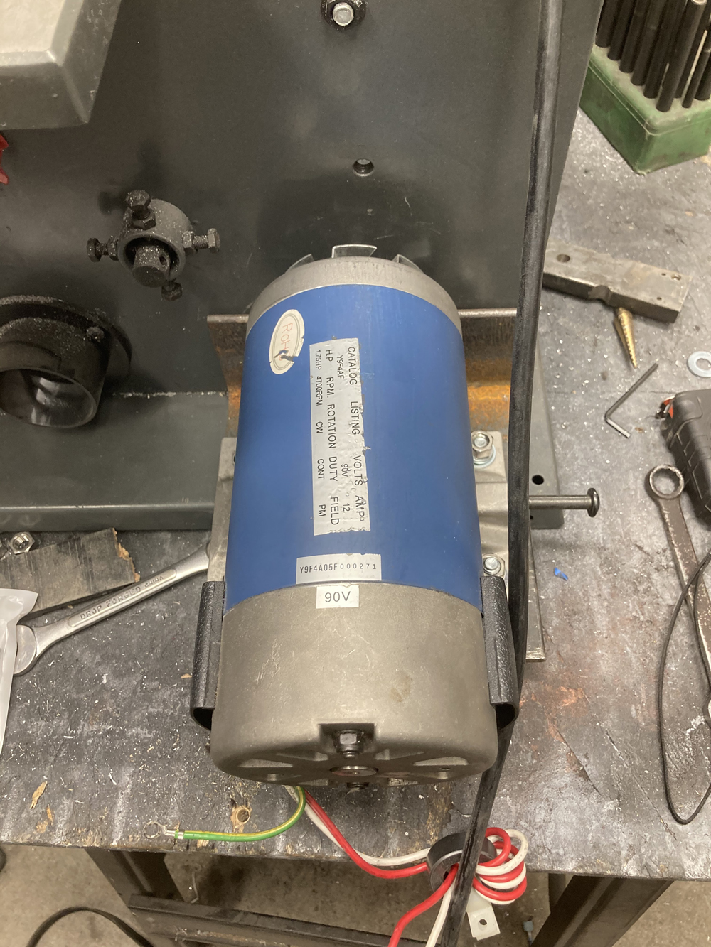
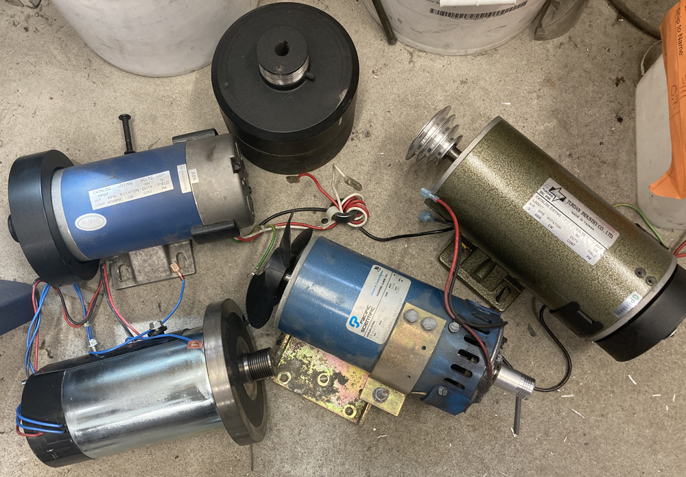
Motors:
As I said before I took apart 5 different treadmills and they had 5
totally different motors. They ranged in amperage from 1.5-3 amps
and 1-3 horse power. All 5 of them were rated for about 4000
RPMS. Some were set up for clockwise rotation and some were set
up counterclockwise. Good news is almost all treadmill motors are
reversible by simply switching the + and – wires. There is an
exception however where some motors are not reversible. To know if your
motor is non reversible there is a simple test, rotate the shaft by
hand in the direction indicated on the motor label. It should
easily spin but will probably have a slight “pulsing” feeling as you
turn it. Then rotate the motor the other direction if it feels
the same it is reversible if it catches and turns much harder it is not
reversible.
All
treadmill motors come with heavy flywheels and depending on your
application, you may choose to use them or not. Some
flywheels are threaded on and some attach using set screws and
keyways. If the flywheel is threaded on keep in mind the motor
can only be spun one direction while using the flywheel, as spinning it
the other direction will unthread the flywheel from the shaft.
Even though all these treadmill motors are basically the same and are
setup the same way there are some wire differences to be aware
of. The colors you may see are red, black, white, green and
blue. The red wire is universal across every motor I have seen
and is the + wire if you want the motor to spin in the direction on its
spec label. The black wire or white wire is the - wire.
There is no difference between black wires and white wires other than
their color. They are the opposite wire to the red wire.
The green wire is the safety ground. Some videos I have watched
tell you, “You don't need the green wire so clip it off.” This is
horrible advice. The green wire is there to ground the body of
the motor to the body of whatever you are installing the motor on and
to ground it to the ground prong in the wall outlet. Electricity
takes the path of least resistance and if something goes wrong this
green wire provides that path. If one of the power leads rubs up
against the body of the tool and the insulation becomes damaged you
have a situation where electricity can be flowing through the body of
the tool. If the green wire is installed it will create a direct
short and trip the circuit breaker. If the green wire is not
installed, electricity accidently begins flowing through the body of
the tool and you touch the tool your body may provide the path of least
resistance resulting in electrical shock. The green wire is there
for safety. USE IT. Blue wires are also safety wires, and
again I have heard videos that say, “You don’t need the blue wires so
clip them off” this is again bad advice. The blue wires go to a thermal
fuse inside the motor and that fuse is designed to be part of the AC
circuit between the on/off switch and the speed controller. If
the motor over heats the thermal fuse trips cutting power to the motor
controller. An over heating motor will burn up so by using this
feature you help eliminate that possibility.
Switches, rectifiers, fuses, and circuit breakers:
Seams fairly strait forward, you need an on/off switch to cut power to
the speed controller and from there you wire up the motor and you are
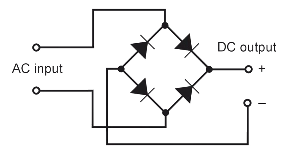
good to go. There is more to it than that. First when using
an SCR power supply you must, as I said above, use a bridge rectifier
to convert the AC to DC. A bridge rectifier is basically a single
component with 4 diodes inside.
AC
which stands for alternating current gets its name because the two
power wires alternate from positive to negative 60 times a second
opposite of each other. A bridge rectifier takes that input from the
alternating current and shunts all the positive current from both wires
to one terminal and the negative terminal returns the current to both
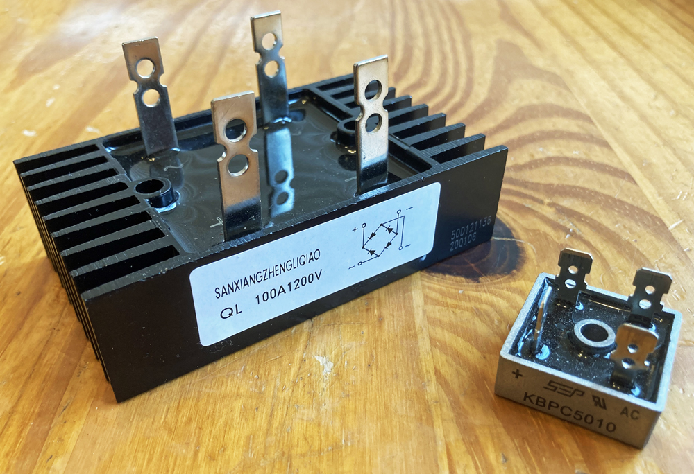
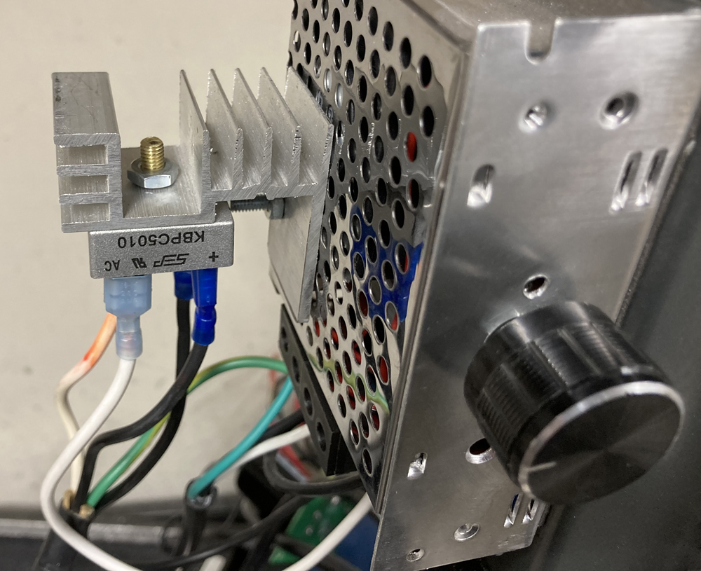
wires converting AC to DC. I used a KBPC5010 bridge rectifier
which is rated at 50amps and 1000 volts way above what we are needing
to run a treadmill motor. Again I went bigger to maximize life of the
component.
It is important to know, when
a bridge rectifier fails it typically shorts out across all 4
terminals. When I first started this project I purchased 5 rectifiers
from a supplier and with all 5 when a load was applied, even though the
voltage and amperage was way less than what the rectifier was rated at,
the rectifier would fail shorting out all 4 terminals which in turn
would overload the speed controller burning it out. This problem
could have easily been avoided by adding a 20 amp fuse or 20 amp
circuit breaker on the non common lead between the rectifier and the
power supply. It is also a good idea to add a fuse or circuit
breaker between the power supply and the on/off switch.
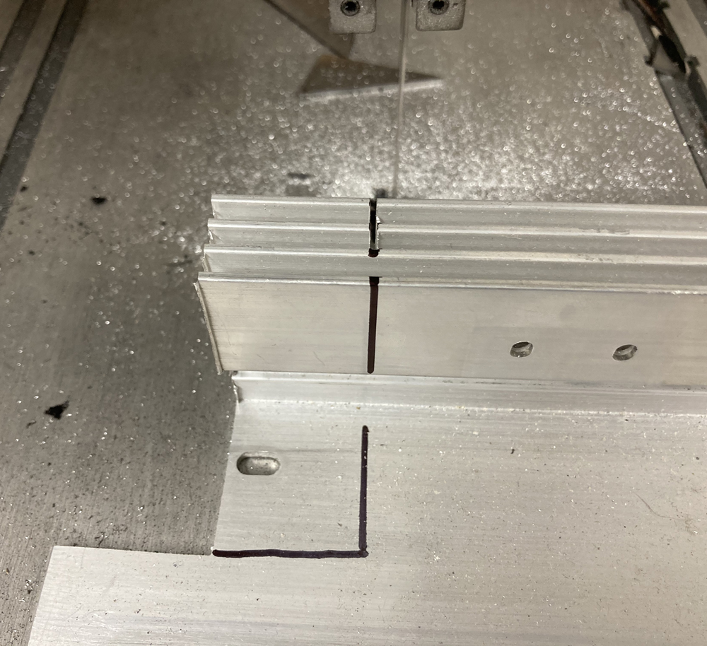
It is important to know that bridge rectifiers produce heat as a
byproduct of them converting AC to DC. I recommend using a heat
sink to help dissipate that heat. I made mine by cutting a
section out of one of the heatsinks from a non usable control boards
scavenged from the treadmills.
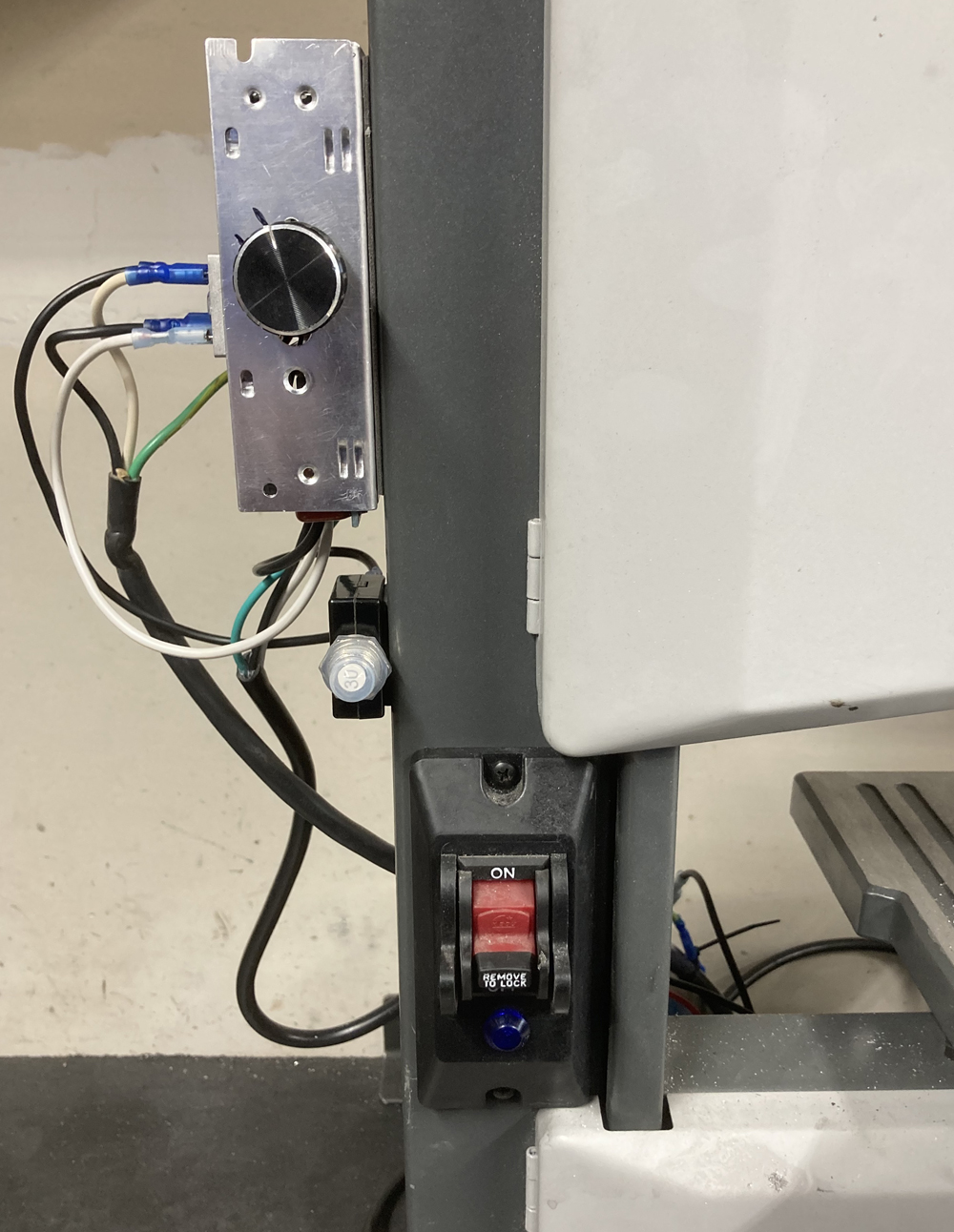
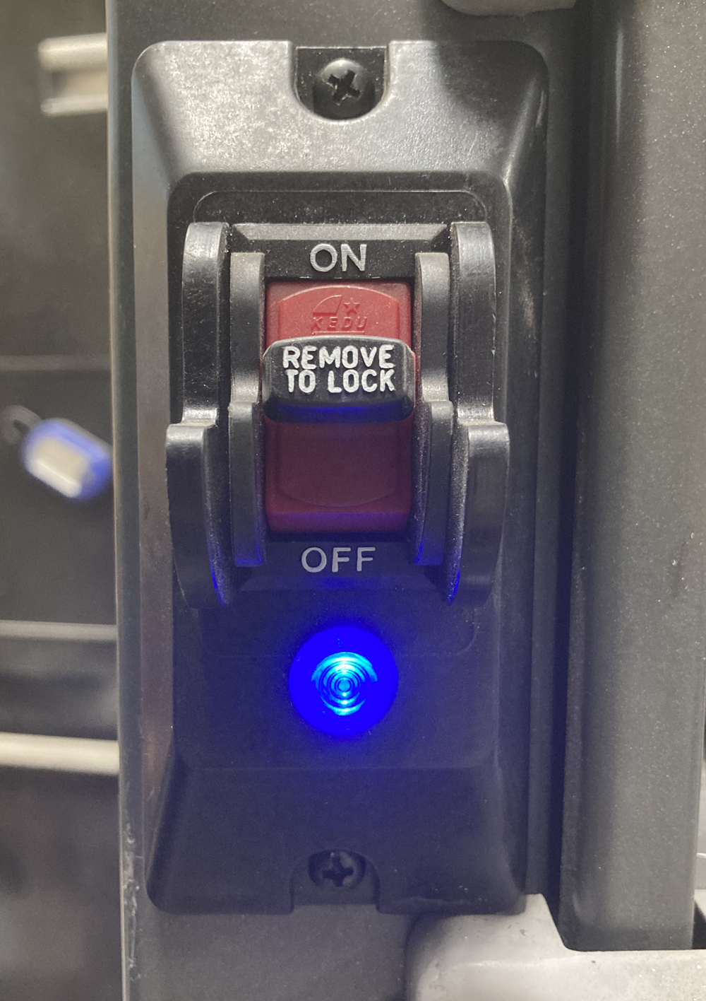
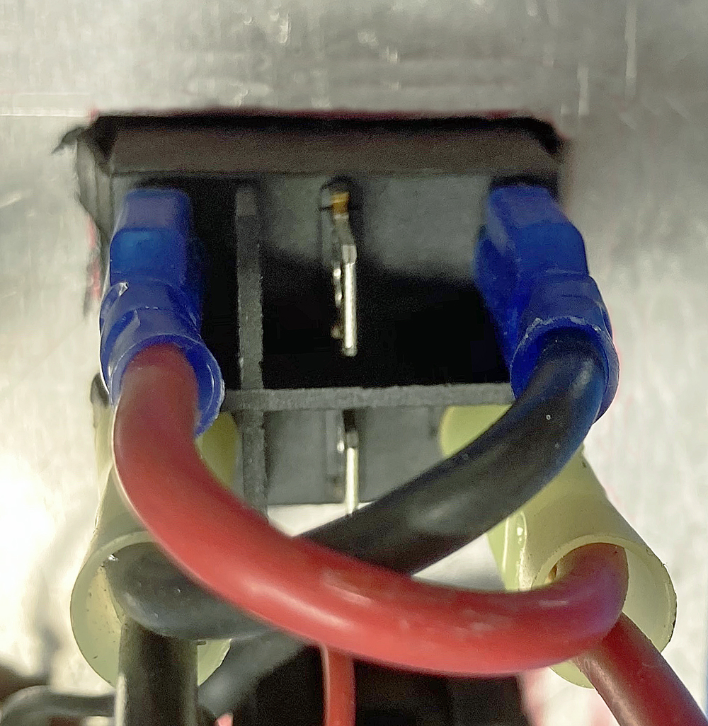
Proper gauged wire and AC LED indicator lights:
There are a couple of other safety things that I would recommend.
The first (a good tip I got from YouTube) is an LED indicator light on
your main power switch. When there is power being supplied to the
speed controller the light will be on. This is nice especially if
you don’t have the correct potentiometer in the controller. I say
this because turning the knob down past the “minimum” speed could
cause the motor to stop even though everything is still on. The
LED as an indicator lets you know the system is still on and to shut it
off when not in use. Failure to turn the power off when not in
use could burn up the speed controller, the rectifier, and or the Motor.
One
other thing to note is just because the power cord came with the tool
you are putting the new motor on doesn’t mean it is up to the task of
powering the new motor. When I first set up my band saw I used the
original power wire and after the conversion I noticed it getting warm
when running the saw. Upon further inspection I discovered the
wire was way to small at 18 awg. 14 awg is rated at 15 amps and
is the minimum I would use.
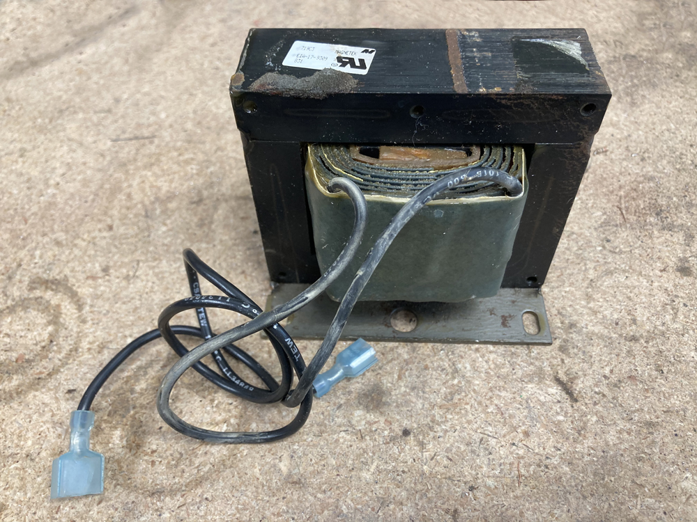
Chokes:
The most important thing for improving function and prolonging motor life is a large DC choke and you really need to run
one (another good tip I got from YouTube but something I was able to
verify by trying the setup with and without them). Some
treadmills come with them. They look a lot like transformers but
are not.
They
have two wires, an in and an out and when attached inline between the
positive terminal from the rectifier and the motor
they will SIGNIFICANTLY improve motor function. I have again
heard it said “throw them away you don’t need them” and while to some
degree that is true it is again bad advice. When hooked up the
choke reduces the noise produced by the power supply and motor by at
least half. Not only does it reduce noise but it also
eliminates almost all sparking inside the motor. There is a
direct correlation between noise/sparking and motor life so if you have
one why wouldn’t you hook it up to prolong the life of your motor.
Also there was one more
observation that showed the value of the large choke between the
rectifier and the motor. When I set up my lathe with one of these
motors I did not originally use the choke. When I turned the
lathe on with speed control set at slower speeds there was no problem,
but if the speed control was all the way up to full and I turned the
lathe on the 15amp circuit breaker for the wall outlet that system was
plugged into would trip. After I installed the choke I
could turn the lathe on at any speed and the circuit breaker would not
trip.
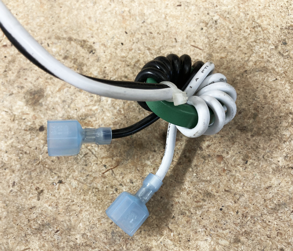
There are also smaller AC chokes that you may find in some treadmills that
are as simple as too wires wound around a ferrite donut, usually
not more than 1.5” wide.
These are better for the AC side. You need to put it between the SCR power supply and the rectifier. With this combination you are "cleaning" the current coming out of the SCR with the AC choke and then once again cleaning the current coming out of the rectifier with the DC choke. The end result, clean power.
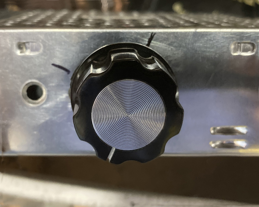
Setting up the potentiometer for speed control:
The last component we need to address is the potentiometer. This
is the dial we turn to control speed. Same part that I wired to
the H, W, and L terminals on the MC boards. The SCR controllers
come with a potentiometer already installed however all the controllers
I purchased, with the exception of the push button unit, had a
potentiometer that is way to big. The result of using an over
sized potentiometer is you have to turn the knob 1/3 of its total
rotation before the motor comes on and then you only have the last 2/3
of the knob movement to adjust speed. This makes the knob very
sensitive where very little movement makes a big change in motor
speed. The advice I found on line was to use trial and error to
find a potentiometer that will work for your application.
However, this is again in my opinion, not good advice. There is a much
easier way to get exactly what you need. To know what size you
will need, start with the SCR controller as it came from the supplier
with the over sized potentiometer. Wire the speed controller up to the
motor, power the system on, and turn the Knob until the motor coms
on. Mark the body of the controller so you know where the knob
needs to be to turn the motor on. Then with the system unplugged
remove the cover of the power supply and use a meter to check the
values of the potentiometer at the marked point. Both of the knob
stile power supplies I purchased had 500K Ω potentiometers
installed. On the cheaper unit the potentiometer had to be turned
to 120KΩ for the motor to come on. That means 120KΩ potentiometer
will give you full speed control with that supply. The better
supply with the built in cooling fan measured at 150KΩ at the marked
point so 150KΩ potentiometer was needed to give full speed control.
But what if you don’t want full speed? All of the motors I have
are rated around 4000RPMs at between 90v and 110V DC. The
AC motor on my band saw was rated at 1700 RPMs and spinning a treadmill
motor at 4000 RPMS would be more than double that and at the very least
probably cause the tool to fail and more likely cause injury. If
you allow the speed controller to have an option for full speed there
is the chance that you will accidently turn the speed up to much.
This danger can be easily eliminated. To do so I used my RPM
meter and my volt ohm meter. Using the RPM meter I turned the
knob on the potentiometer (Again the one that came in the SCR unit)
until the motor reached the max speed I was looking for of
1700RPMs. I then made a second mark on the body of the power
supply to show me the knob location for the max speed I was
after.
From
there I powered down the system removed the speed control cover and
used the volt ohm meter to measure the potentiometer rating at the two
marks: start speed, and max speed. As I said above start speed
was 150KΩ and target max speed mark was 100KΩ. That meant I
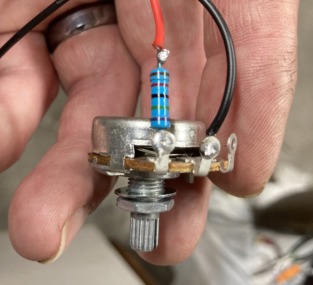
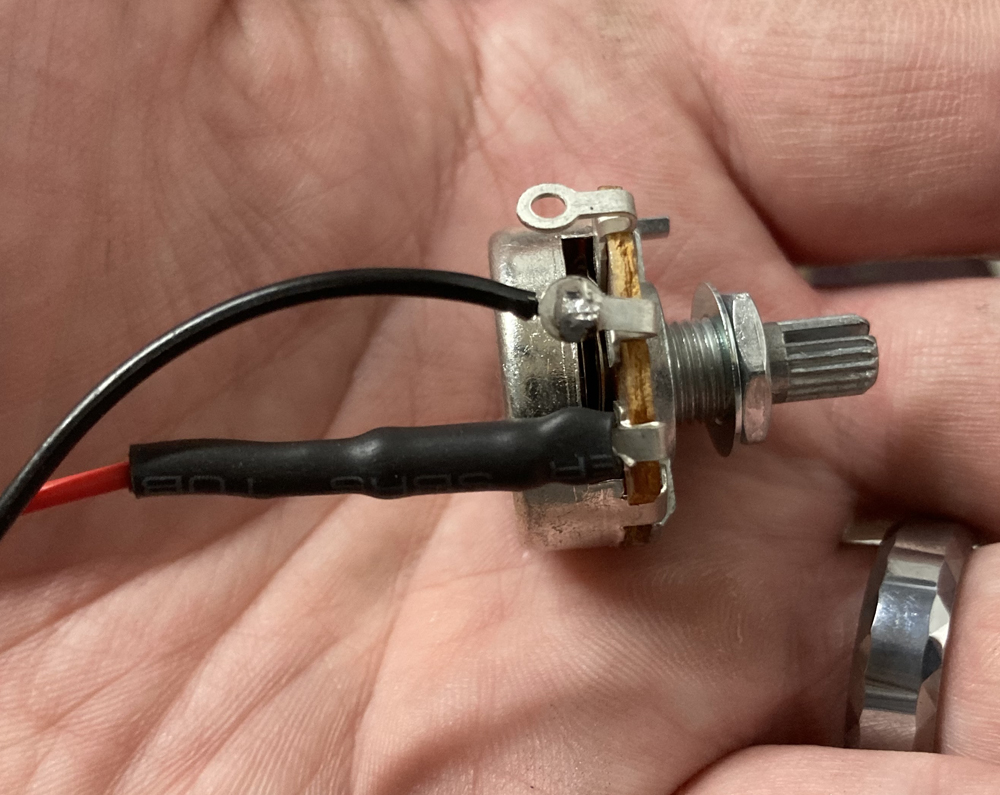
needed 50kΩ of adjustability and a minimum Ω of 100. This was
easily achieved by putting a 100KΩ resister inline between one of the
wires and one of the terminals on a 50KΩ potentiometer. Resisters
(a potentiometer is a variable resister with its max being its rating
and then it can be reduced down to 0) when wired in series add their
values together. When the potentiometer is at 50KΩ the total of
it and the 100KΩ resister is 150KΩ when the potentiometer is at 0Ω the
total is 100KΩ giving me full adjustability between starting speed and
my desired max speed.
I used some shrink tubing over the resister and terminal end to insulate it and give it some regidity.
One
important thing to note before marking max and min speed so you can
measure the Ω Get the motor mounted up and driving whatever it is going
to drive. Belts and pulleys will absorb some energy and reduce
RPMs. For example 100KΩ made a max speed of the motor I was using 2000
RPMS when nothing was attached to it but once hooked up to the band saw
that same amount of resistance gave me a speed of 1700 RPMs.
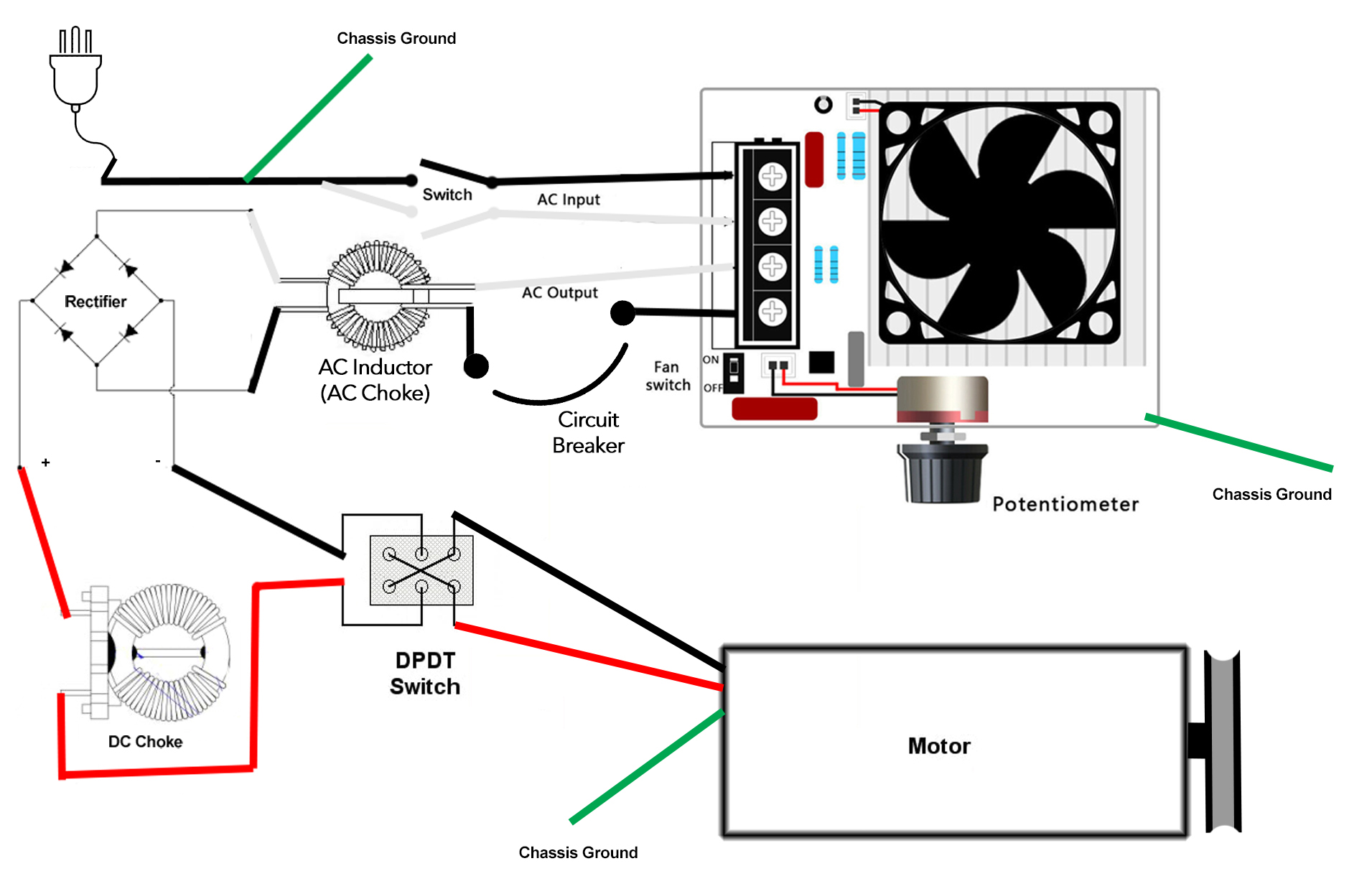
SCR Wiring diagram:
Tips and tricks for using the RPM meter:
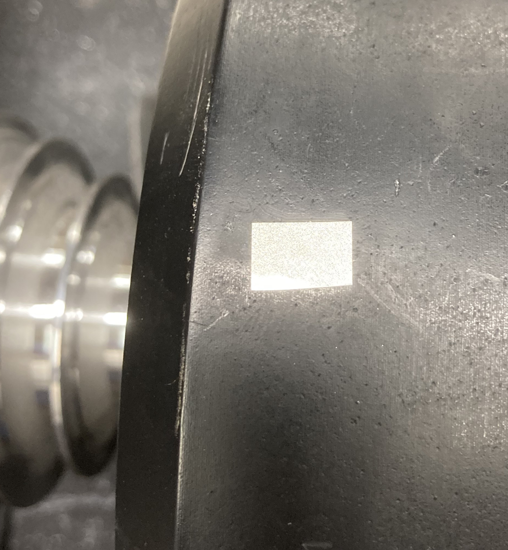
As I said in the beginning the RPM meter works by placing a piece of
reflective tape on the rotating assembly. The Meter then uses
inferred and the reflection from the tape to calculate speed.
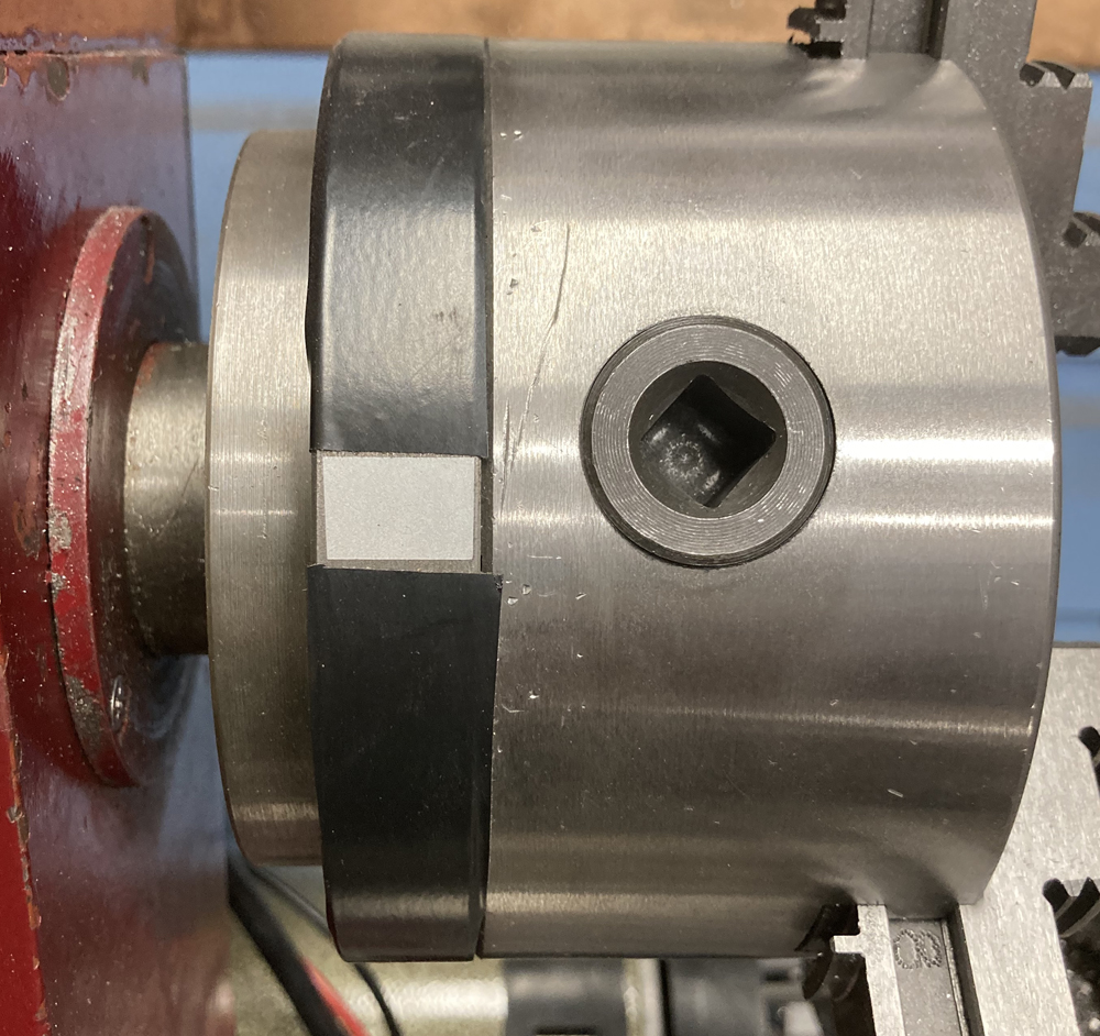
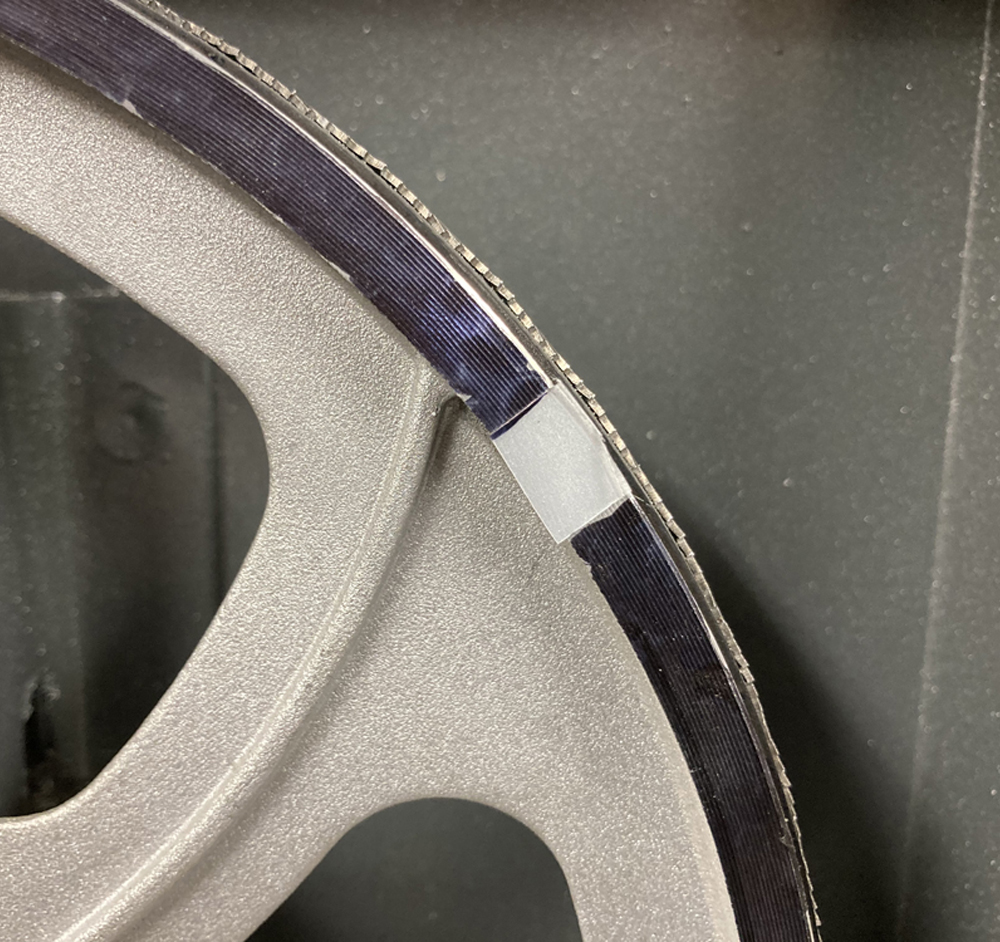
If
you are putting the tape on something silver (bare steel or bare
aluminum) you will not get an accurate reading. A couple
solutions are to use electritions tape around the rotating assembly (I
did this on my lathe chuck) or take a black marker to the surface (I
did this on my bandsaw wheel)
Hooking it up to my band saw:
Now with all the technical info out of the way lets look at how I put
it all in to practice in the application of my 9” band saw
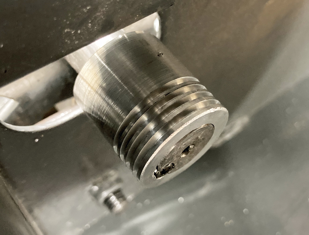
I started by machining a pulley out of aluminum to fit on the treadmill
motor shaft that matched the belt that the band saw came with.
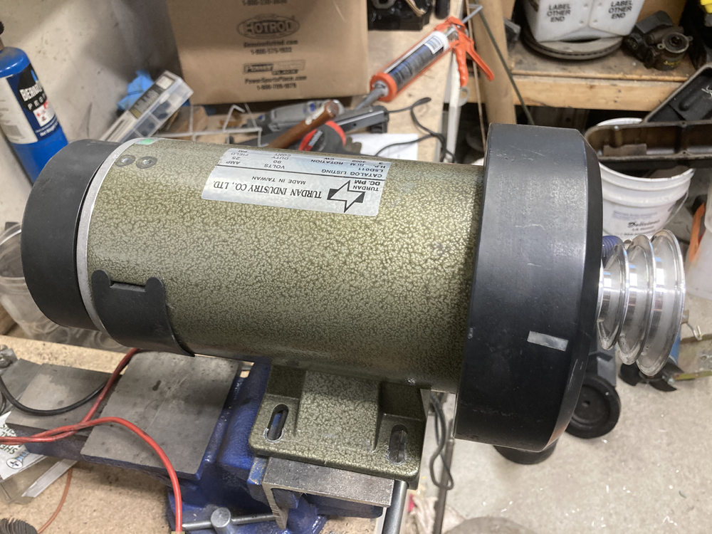
I
then mounted the motor to the back of the saw in the same location that
the original AC motor had been in. The treadmill motor was about
the same diameter but almost twice as long.
The
belt was then installed and I turned to wiring it up. I attached the
SCR controller to the side of the saw ran the ac output to a circuit
breaker and from there connected it to the rectifier. The power
conection refered to ascommon went directly from output on the SCR to
the rectifier. From the rectifier the positive wire went through
a choke and from there to the motor and the negative wire went directly
from the rectifier to the motor. With everything wired up I
powered up the system, found my min and max as described above and
replaced the potentiometer with the correct one in conjunction with a
resister.
System works very well and I
am extremely happy with it. I have used the saw to cut all kinds
of things including steel.
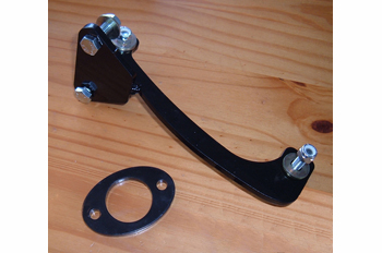
Lathe:
This is the biggest motor I have and I put it on my Lathe/mill. 3 HP
This
project was almost the same as the band saw project with one
exception. On a lathe I needed to be able to reverse
direction. Reversing the positive and negative wires between the
rectifier and the motor easily does this. To accomplish this I
used a DPDT switch rated at 30 amps. To hook it up I connected
the motor to the two center pins on the switch. The positive and
negative wires are then hooked up to the outside pins opposite from
each other.
By
doing this when the switch is set to one direction the positive from
the rectifier goes to the positive on the motor and the negative from
the rectifier goes to the negative on the motor giving you the listed
rotation direction, but when you flip the switch the other way it
connects the positive from the rectifier to the negative on the motor
and the negative from the rectifier goes to the positive on the motor
giving you the opposite rotation direction.
I
will also be adding a digital RPM gauge to my lathe. On the band
saw I marked speed values around the dial and then fine-tune based on
cutting performance and sound, but on the lathe I need more accuracy so
by attaching a digital gauge to the tool I will have real-time speed
feedback without having to use the handheld RPM meter.
eBay:
One thing I did before disassembling my treadmills was to plug them in
and test them. It was important to know if they worked so I would
have the option to sell off non needed parts. On two of the
treadmills I was able to take the working control boards out and list
them on eBay. I sold the boards for $35.00 each. This is a
good way to get back some of the initial investment of purchasing a
used treadmill.
Update 01/11/2021:
I have been using this setup on both my lathe and bandsaw for several
months now and am very happy with the way they are working. I did
run into one small issue. On both machines I had a bridge
rectifier failure. These motors draw less than 30 amps at 0-110
volts and the original bridge rectifier I used was raited at 50 amps up
to 1000 volts. Also the bridge rectifier I chose had been used by
others with success. This coupled with the fact that my first
batch of bridge rectifier all failed with little to no load leads
me to believe there are some manufacturing issues with these
parts. To fix the issue I went with a 100 amp 1600V bridge
rectifier normaly used in a welder. It comes with a heatsink
built in and only cost me about $7.00 from Amazon. This is a far
beter option and what I would recomend in the future. As you can
see below the 100 amp bridge rectifieris way bigger size wise than the
50 amp unit I started with.


 SCR Controller 3