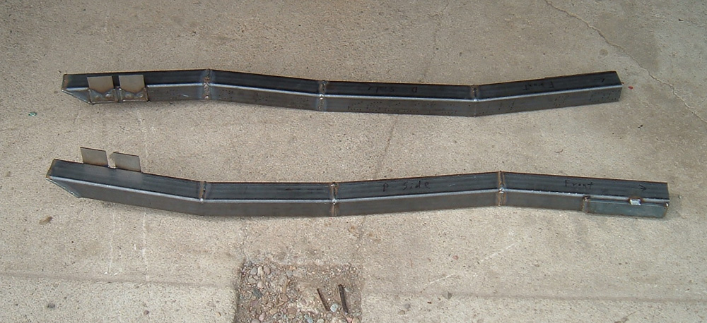
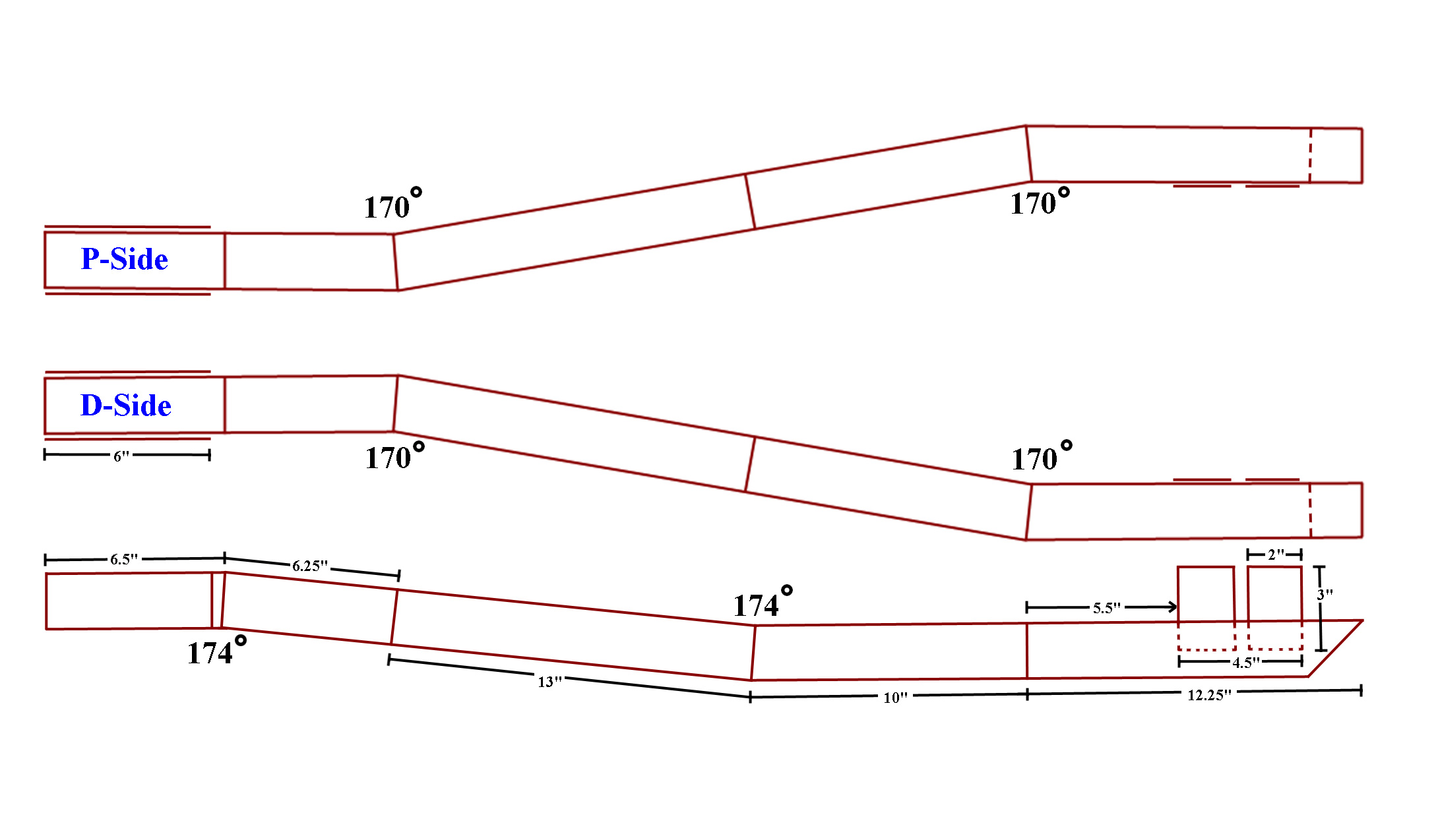
Plans for building
connectors for a
64.5-73 coupe or fastback. The bottom drawing is the side view
and the top drawings are the top view of both connectors D-side and
P-side respectievly.
A
quality set of connectors, that fit like they were Ford designed
original equipment, can be fabricated with basic tools skills and a
very little money.
The
Mustang is a sports car? The
Mustang has the heart of a lion with
the sleek sporty lines to rival any sports car, but it is built on the
chassis of a 4-door family car, the Ford Falcon. In other words,
when it comes to chassis performance, specifically in handling, the
Mustang has LOTS of room for improvement. One attribute of the
Mustang that it definitely gets from it roots in the Falcon, is the
unibody design. Basically, unibody means that the car does not have a
solid frame running full length of the car from the front to
rear. The lack of a frame is accomplished by short frame rails at
the front to attach the motor to and frame rails at the rear to attach
the rear end to. Connecting these two sets of frame stubs is
nothing more than the body of the car, more specifically the cab. Ford
and many other manufacturers used this design because it was cheaper to
build and lighter. The problem with this design is that the body
must hold its own weight and react to ever changing road
conditions. Off of the factory floor, the unibody design of the
Mustang worked well, but over the last forty years, daily abuse coupled
with rust in key locations, can cause a car to sag in the middle.
Even if the car does not sag, if you look at any unrestored early
Mustang, you will find a crack at the rear base just below the rear
side windows on one or both sides. This is the result of flex in
the unibody. One simple fix to improve the overall structural integrity
of a Mustang, and a must for any Mustang that is going to be used in
performance applications, is to install sub-frame connectors that join
the front and rear frame rails, making the frame a solid unit that runs
the full length of the car.
Sub-frame connectors are such a
popular
upgrade that there is a host of options in the aftermarket, from
generic pieces of steel with no bends, tubular units, and other options
designed to contour the underside of the car and more aesthetically
mimic a solid square tube frame. Although the aftermarket offers
both weld-in and bolt-in sub-frame connectors, the walls of the front
and rear stub frames on the Mustang are so thin that bolt-in options
are ineffective. NOTE:
in my humble
opinion ALL, sub-frame connectors, even the bolt-in kind, need to be
welded into place. A person can spend quite a bit of money
on sub-frame connectors, but for less money a quality set of connectors
that fit like they were Ford designed original equipment can be
fabricated with $25.00 in steel, basic skills, simple cutting tools, a
welder and the following information. NOTE: the
following info is for building connectors for a 64.5-73 coupe or
fastback and does not directly apply to convertibles, due to torque
boxes under the car.
Before
you start this project you need
to evaluate your welding skills. The following is the process for
constructing an intrical part of the Mustang support frame and if your
welding skills are not sufficient for the task, catastrophic failure
could occur. NOTE: If
you have any doubts AT ALL about your welding skills, DO NOT ATTEMPT TO
MAKE YOUR OWN SUB-FRAME CONNECTORS!! One option for the
non-welder is to prep the materials and then take them to a certified
welder for assembly and instelation.
Tools required:
Cutting tool
Angle grinder
Welder
Angle finder
Tape measure
Materials required:
2” x 1/8” plate
steel, about 4 feet
2” square tubing 1/8” walls 8’
Fabrication
Process:
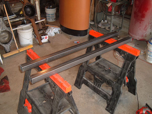
The first step is to cut two 4’
pieces
of the 2” square tubing. Once the pieces are cut, they need to be
marked at the points where the connectors need to be bent. I made
the marks on all four sides of the tubing at all four bend
locations. The first measurement is 6.5” from the front, the
second measurement is 12.75” from the front, the third measurement is
25.75” from the front and the fourth measurement is 35.75” from the
front, which should leave 12.25” from the last measurement to the end
of the tubing. Each one of these measurements is going to be a
bend in the tubing. Once you have the original measurement marks,
additional marks need to be made so that notches can be cut out of the
tubing. When the notches have been put in and the tubing has been bent,
the final result of the bending needs to be that the first and third
bends are 174 degrees and the second and fourth bends are 170
degrees. The first bend needs to be down, the second bend needs
to be towards the outside of the car, the third bend needs to be up and
the last bend is towards the inside of the car. To best
achieve proper angles and consistency, two things need to happen.
The first thing is that the correct wedges of material need to be cut
from the tubing and the second is that a jig needs to be made to ensure
uniform angles, which will be discussed later.
When it comes to the proper wedge
thickness being removed, the 174 degree bends need to have a 1⁄4” of
material removed from the inside of the bend, and in the same way the
170 degree bends need to have 3/8” of material removed from the inside
of the bend. To achieve this I split the distances, either 1⁄4”
or
3/8” depending on the bend I was working on, putting lines on either
side of the four bend marks I had already made. I then drew
angled lines from the edge of the lines I had just made to the
centerline on the outside of the bend. NOTE: on an individual
connector, the first and third bends need to be opposite of each other,
as do the second and fourth bends.When comparing the
drivers side and passengers side connectors, the first and third bends
will be the same on both connectors, however the second and fourth
bends need to be mirror opposites of each other. It is the second
and fourth bends that determine whether or not you are making a drivers or
passengers side connector. Once the wedges have been marked, the
wedge needs to be cut out. This can be done several different
ways ranging from a chop saw set at an angle to a cut off wheel or
reciprocating saw. It is important that when cutting the wedge
you DO NOT cut through the bottom side. For best results cut down
to the inside of the wall on the bottom side. Once the wedge has
been cut out, I recommend grinding an angle on the cut edges to insure
proper weld penetration. Also, grinding the edges makes it so
that when the edges come together they form a trough, which allows the
welds to not protrude very far past the surface of the steel and if one
chooses to grind the welds smooth after the connectors have been
finished, most of the weld bead will remain intact. Before the
connector has been bent and welded, I recommend cutting a 45-degree
angle on the bottom side of the connector in the end to make a smoother
transition to the rear frame rail. Once the steel has been prepped, it
can be placed on two sawhorses, with the top of the wedge up and then
pressed down to the correct angle, closing the wedge and then tack
welded into place.
When bending the steel, for
best
results, the sub-frame connectors MUST be identical in retrospect to
the corresponding angle on a single connector, as well as the
corresponding angles on the other connector. In other words, for
best results, the four 170 degree bends (two per connector) need to be
identical, even if the bends are + or – a degree or two, you want all
four bends to be exactly the same (same thing applies to the 174 degree
angles). The easiest way to achieve uniform angles is to build a
jig out of a scrap piece of 2” high wood or steel that is firmly
connected at the angle you want. That way the jig and the connector you
are working on can be placed side by side on two saw horses and the
connector you are bending can be bent to match the jig.
Obviously, two different jigs will need to be made since there are two
different angles. To build said jig, place the steel tubing or wood in
a chop saw, set the saw at 5 degrees off of 90 for the 170 degree jig
and 3 degrees off of 90 for the 174 degree jig. Then take one of
the cut pieces and rotate it 180 degrees and then match its face to the
face of the other cut piece so that they can be lined up to achieve the
desired angle, and firmly attach the two pieces together via welding or
glue, depending on the material you are using. Once you have the
jig, place the notched connector next to the jig and bend the
connector, closing up the gap. The connector needs to be bent to
the point where both sides are parallel with the two parts of the jig,
and then tack weld the corners. If there is a slight gap between the
two sides, it is not a problem because the gap can be welded
closed. After tack welding the bend, double check again and make
sure the jig and connector are the same and that the correct jig was
used for the bend. Once the bend has been deemed accurate, you
can weld it closed. Once all four bends have been
made, the
only thing left to do is attach a cover plate on the back angled cut
2.5” long 1/8” thick and 2’ wide, two side attaching plates on the end
3” long 1/8” thick and 2” wide and two spacer plates on either side in
the front 6” long 1/8” thick and 2” wide. The end plate needs to
be positioned over the angled cut end and welded up on all four sides
so that water and road debris cannot get inside the connector.
The attaching plate closest to the front of the connector needs to be
5.5” from the last weld with 1” of material on the connector and the
second attaching plate needs to be 1⁄2” from the first. I use two
plates rather than one large one to have more surface edge area to weld
to. The spacer plates are spot welded to the front in several
locations. The connectors can now be painted leaving any metal that
needs to be welded exposed. The connectors are now finished and can be
installed using the following instructions.
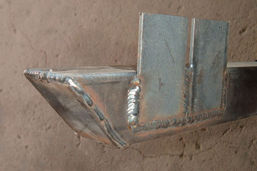
Two
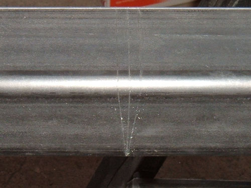
pieces of 2" square tubing 4' long are used to make the connectors The V-notch
has been scribed
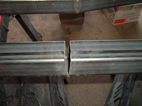
in to the tubing Once the notch has been cut out
the edges can be beveled for better weld penetration. The connector needs to be
placed next to the jig and bent. Once the correct angle has
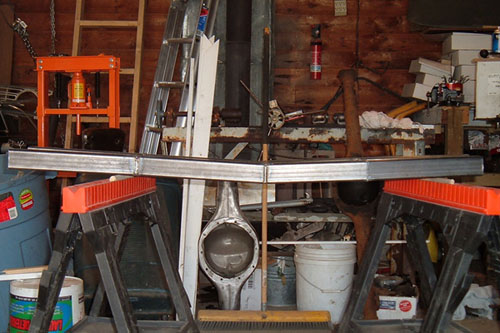
been achieved the notch can be tack welded closed. Front spacer plates welded to
the sides Rear mounting plates and end cap
Cap ends of the front frame rails have been removed
Installed P-side connector
Installation
Instructions
Before
you begin the installation process you need to make sure the surface
the car is sitting on is level and that the car’s
full weight is on its wheels.
1. In each front frame rail, drill three 3/8” holes
in a triangle pattern, approximately centered, in an area between
the end cap and a measurement 6” forward from said end cap.
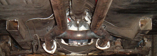
2. When properly installed the sub-frame connectors
slide into the OEM front frame rails, this requires you to cut the caps
off of the OEM rails. It is important you cut them just big
enough to slide the connector in and that you leave a small bit of the
cap at the top to seal the gap between the sub-frame connector and the
floor of the car. For best results cut off less then you think
will need to be removed for a snug fit, test fit, and repeat until you
get a nice sold fit.
3. Once you have the sub-frame connectors fitting
snugly position them so that the two side mounting spacer plates are
almost completely inside the front frame rail. With the sub-frame
connectors in place mark the front and rear frame-mounting locations on
the car to indicate where the sub-frame connectors will be welded
in. Remove the sub-frame connectors then clean and prep the
marked areas for welding. You can then reinstall the sub-frame
connectors and tack weld them in place. Use only a few tack welds
so you can make fitment adjustments with the goal of making the
connectors mirror image of each other.
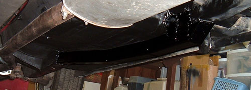
5. With the sub-frame connectors tacked in place,
rosette weld (plug weld) the three 3/8” holes on each OEM frame rail,
weld up the edge where the front frame rail pocket meets the sub-frame
connecter and fill any gaps between the sub-frame connectors and the
front frame rails.
6. Weld around the rear mounting tabs, and place a
stitch weld between the non-bracketed side of the sub-frame connector
where it meets the rear frame rail. Failure to stitch weld in
this location may cause you to punch through the OEM material.
7. To further improve the connection between the unibody and the
frail rails several sheet metal angle iron brackets can be place where
the connecters meet the floor pans and welded in place.
8. A coat of paint or undercoating is recommended to protect your
freshly installed connectors.
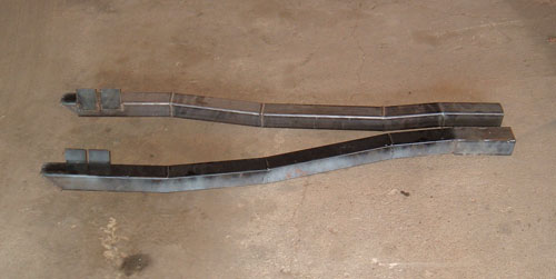
Here we have it, a
completed
pair of sub-frame connectors ready for installation.
Disclaimer on Daze Tech Tips
I am not an expert
in this field. I have performed these modifications myself with very
good results. I am passing along restoration and
performance tips for the purpose of education. If you are
concerned about reliability or safety issues, I do not recommend that
you or any other individual perform these changes or attempt to modify
your cars from stock configuration except under your own
volition. I do not assume nor accept any liability for the
use of
this
information or how it is applied.