 |

I was originally leaning
toward option 2 with option 3 being a fall back
position, but I needed to first mock the suspension up and make sure there were no
other issues before I determined the best answer to the parking brake problem. First mock up: With my car up on the lift there
was no way for me to mock things up without a transmission jack.
I didn't have one when I started this project but a quick call to
harbor freight fixed that problem. With the jack under the car I
used it to roughly position the
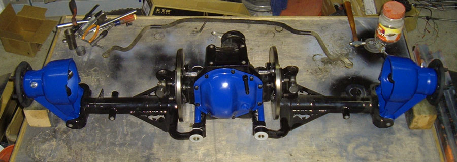
differential into place.
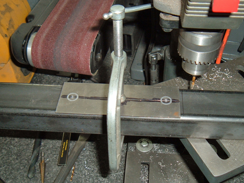
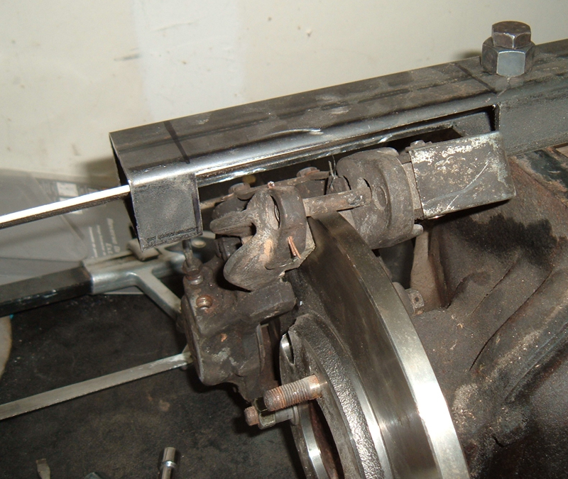
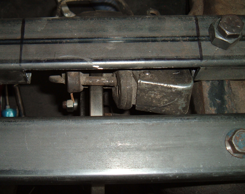
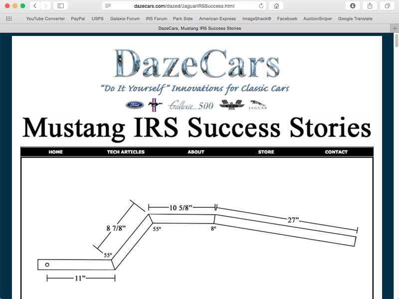
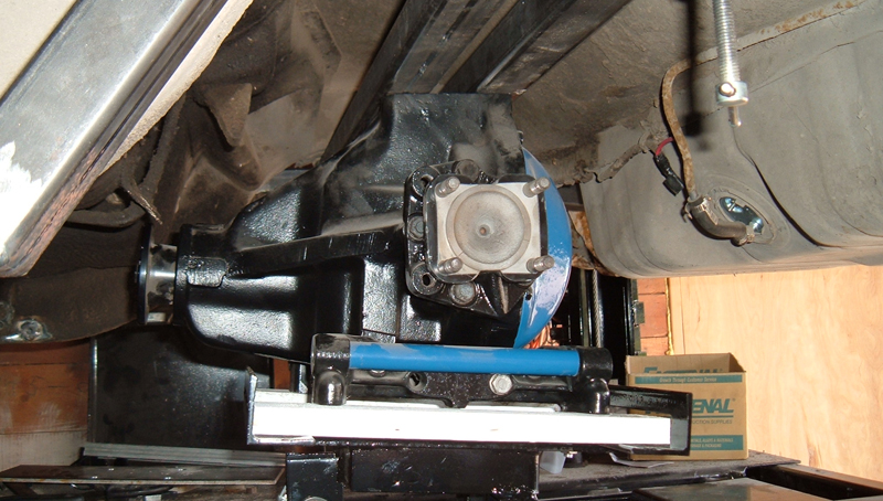 As I mentioned above I was thinking the solution to my parking break issue was to go with a pinion mounted parking brake. After this mock up it was clear that a pinion mounted parking brake would not work as the pinion was to close to the transmission tunnel for the 8" rotor of said brake. So I decided to utilize the factory Jaguar parking brake and to figure out a way to make it work. To accomplish this I had three ideas: 1. Mount the parking brake on the back side of the rotor and attach it to the back crossbar. Easy enough to do in theory, but getting the parts correctly located in relation to the rotor might be a challenge and an incorrectly located system was going to cause pore engagement or worse a sticking brake. 2. Mount the parking brake as designed to the caliper and build a crosbar with a totally different design that clears it. 3. Similar to option 2 in using the Jag parts, notch the front cross support to clear the parking brake assembly and then box it in to account for any weakness the notch created. The back support was not in the way so I would have one solid cross beam and one notched beam. In order to get enough clearance two full sides of my rectangular tubing would need to be removed in the parking brake location and then the rail boxed in creating a triangle tube. I came to the conclusion that boxing the openings should sufficiently reinforce the front crossbar where it was cut. So I decided to notch the crossbar. Another thing that was cleared up in that mock up was the fact that I didn't like is the 6º caster. The picture does not do it justice. I hated the fact that my options were to run a pinion angle that could cause u-joint problems, run the correct pinion angle and have 6º positive caster or compromise. I wanted the correct pinion angle and I wanted the suspension to travel vertically. I figured out how to have both!!! I came up with a solution and will cover it further down in this page. Notching the crossbar to clear the parking brake: To fit the Jag parts to the crossbar, I started by making a two hole template out of flat stock and then used it to drill two holes in a piece of 1.5" X 2" rectangular tubing (same stuff I used for the cross bars) I like using templates because you can check your accuracy before you actually drill in to the final piece and it could be used to reproduce identical hole spacing on many pieces. With the holes drilled I set my scrap piece of rectangular tubing on the differential, and freehanded the approximate area that I needed to cut out to notch the cross bars to clear the parking brake calipers. I Then cut the free handed sections out and bolted the scrap piece on to the diff to adjust the fit. As I was messing with it I looked in to using some 1/8" plate to box in the notch. The only stuff I had was 2" wide and wouldn't you know it was almost a perfect fit!!! I needed to prepare a piece long enough to run the entire length of the cross bar so I cut one to length and drilled two holes in the middle to clear the differential mounting bolts. I was glad I made a template, by the time it was all said and done I drilled 4 sets of holes.
I was pleased with the results and then used my template to drill out the actual back and front cross bares. I bolted the back one up to the differential, with the test scrap I originally notched still bolted up to the differential just to make sure that the caliper cleared it. All looked good. 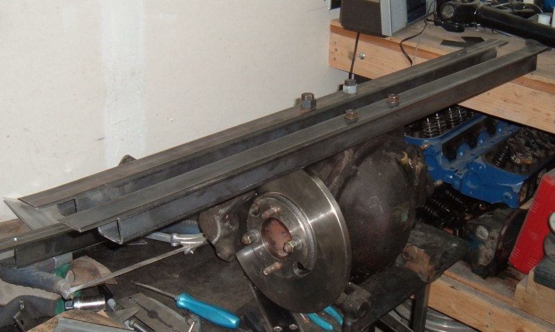 From there I was able to get the actual front cross bar marked for cutting and remove the metal that was in the way.
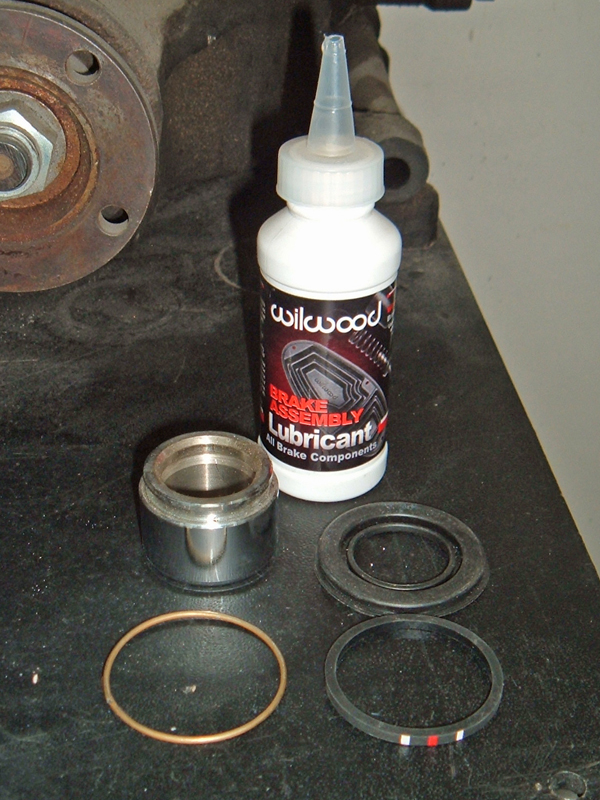
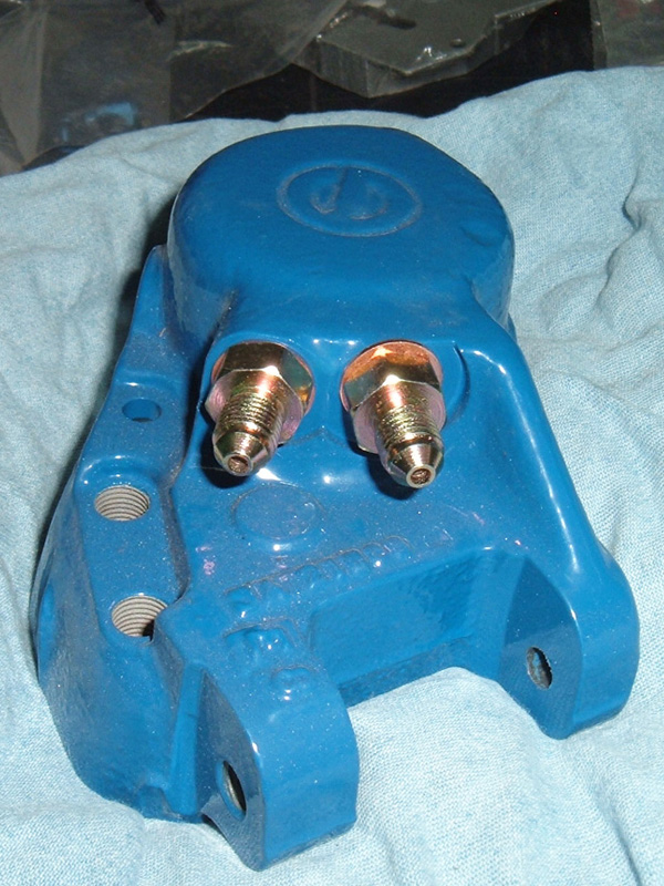
 I am sure glad I had an extra set of rear brake calipers: When I started rebuilding my brake calipers I found they were hard to get apart, and I ended up braking one of the bleeder screws off, also the pistons were all bad. Fortunately I had another set of calipers that came with the second IRS unit I bought and since I will be using XJ40 out board discs on the second set up (it's for my Galaxie) I didn't need the extra calipers. The second set came apart no problem. The pistons probably could have been reused, but I decided to replace them anyway.
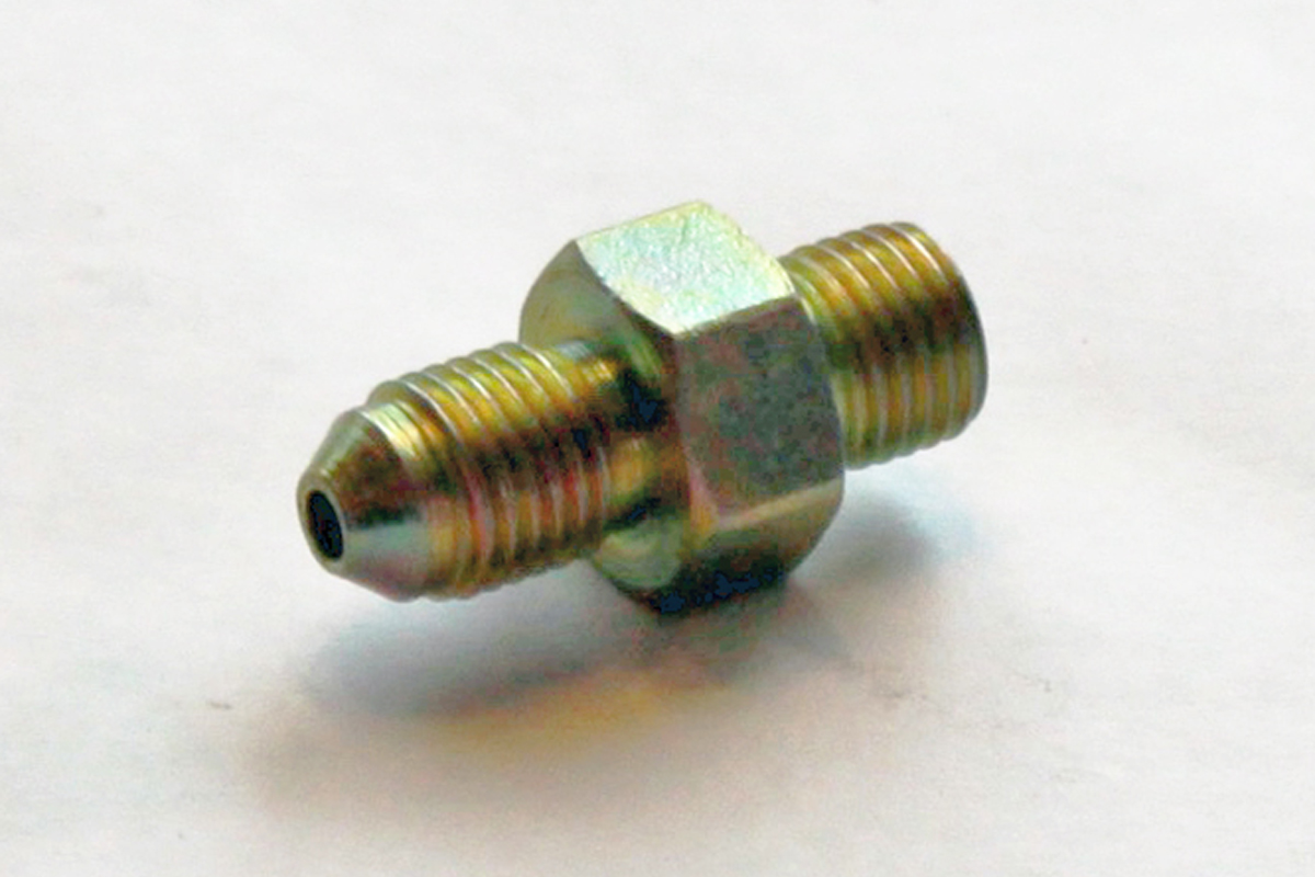
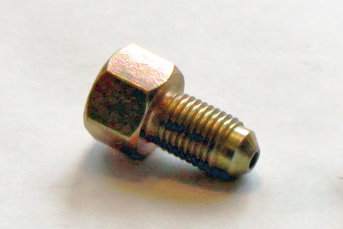
The an-3 adapter requires a coper washer but the inverted flair adapter
will actually seat in the brake calipers without the use of a coper
washer.
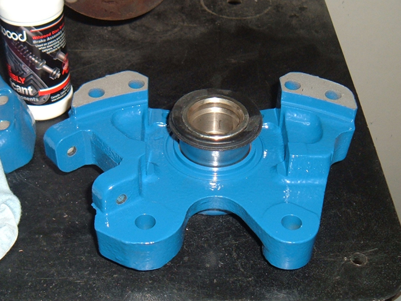
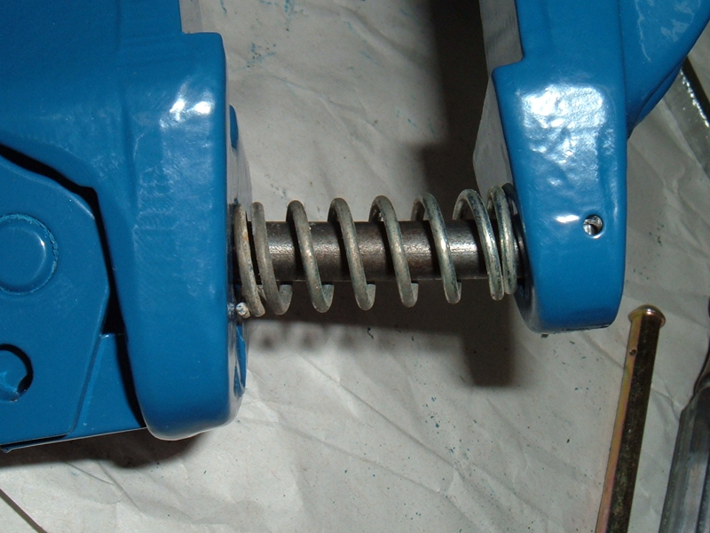
Improving my Jag parking brake system: For those of you who are familiar with the jag parking brake you know that when you disassemble used calipers the pads tend to be unevenly worn and one side of the pad is usually in constant contact with the rotor. also the self adjusting parking mechanisms likes to freeze up. I think I came up with several solutions to eliminate these issues. First I added a spring around the adjuster bolt at the upper part of the mechanism. This in theory should work in conjunction with the brass clip and help push the pads away from the rotor when the parking brake is not engaged. Second I made sure the adjuster bolt threads threaded in to the adjuster extremely easily. I did this by putting a die on the threads and then tightening one side of the three die holding screws so that it tightened the die on to the threads. Once I had it tight enough that there was quite a bit of resistance when I spun the die tool I snugged up the other two die holding screws to secure the die and then ran it down the threads. the result was threads that were a few thousands smaller than normal and an adjuster bolt that freely spun in to the adjuster with no drag. I then added a liberal amount of grease to the thread to help avoid rust and that took up any difference between the adjuster bolt and adjuster resulting in a smooth spinning assembly. 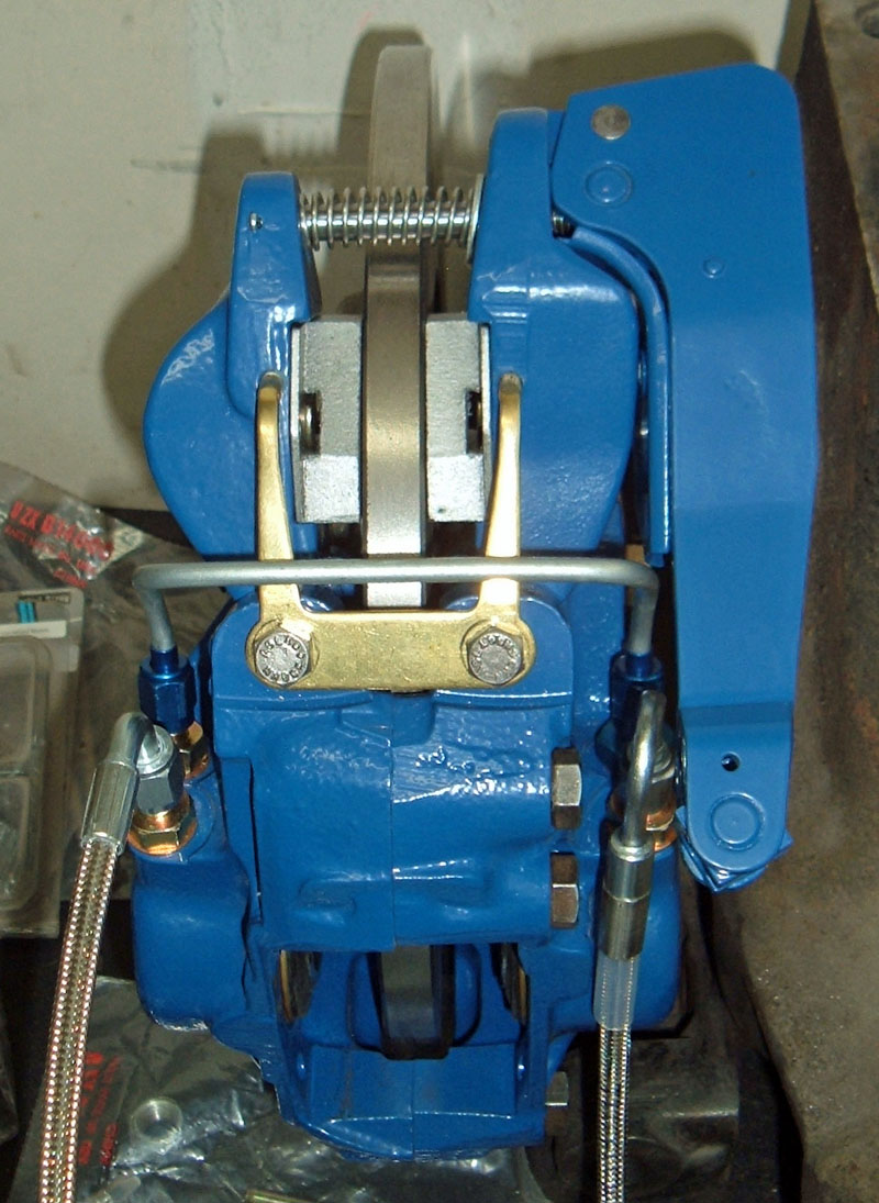 With the rotor out I was able to actuate the parking brake to the point where the pads came in contact with each other and the system worked well, stayed centered and the pads retraced slightly when the parking brake was let off. I will also be liberally greasing the pins that the parking brake parts pivot on because I believe this another failure point. One side will freeze up causing the brass return clip to distort. Over all I think this will be very effective improvement to the original design. I also assembled a remote bleeder set up and will be posting some pix of it on a future page Small problem something was to thick: When I tried to fit the calipers, loaded with pads, to the rotors they didn't fit. Somthing was to thick, either my pads, rotors, caliper pistons, or a combination there of. when I rebuilt my rear Jag calipers I purchased new pistons, new pads and new rotors. When I got it all together I found that the distance between the pistons and the rotor was about .02" thicker than the distance between pads. To fix it I took a flat piece of steel, placed some sand paper on it rough side up and shaved .01 " off of each pad. A solution to the
pinion angle vs. suspension angle
issue
I could not let the compromise between pinion angle and wishbone angle
go so I found a solution that allowed me to maintain the correct
pinion angle to match my transmission and also allowed my suspension to
travel vertically. The solution came from three little letters XKE. I
was going back through my loose leaf binder with the hundreds of pages
of info I have gathered on independent rear suspension and one of the
sections is several pages that came from CWI detailing all the
differences between the various Jaguar IRS parts. One such difference
over the years is the differential side brackets. They came in three
different configurations: The XJ units were drilled to be parallel to
the pinion, the 3.8S or saloon brackets were 3º down in relation to
the pinion and the XKE brackets were 6º down in relation to the pinion
which makes them almost parallel to the top mounting surface. By
running XKE brackets I was able to mount the diff 5º up and have
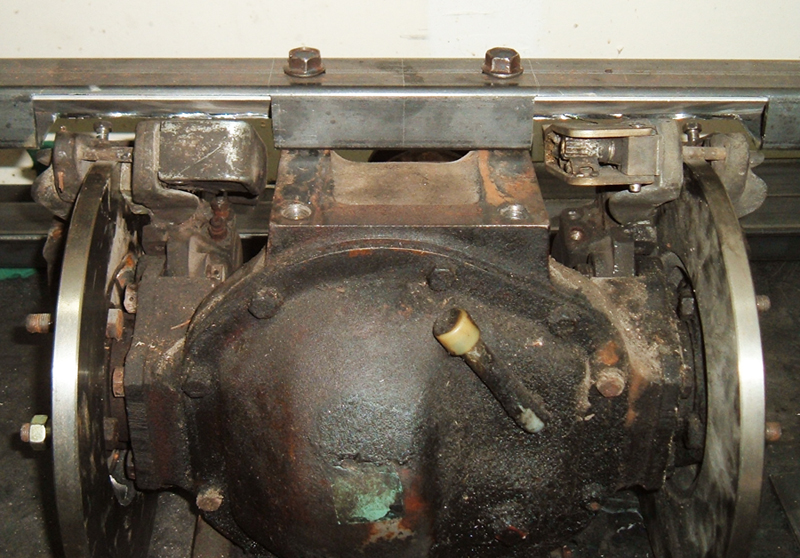
near vertical suspension travel.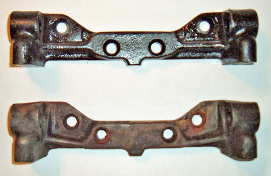 Here is a comparison
between the two brackets. The top bracket is the
XKE bracket and the bottom one came off of an XJ6.
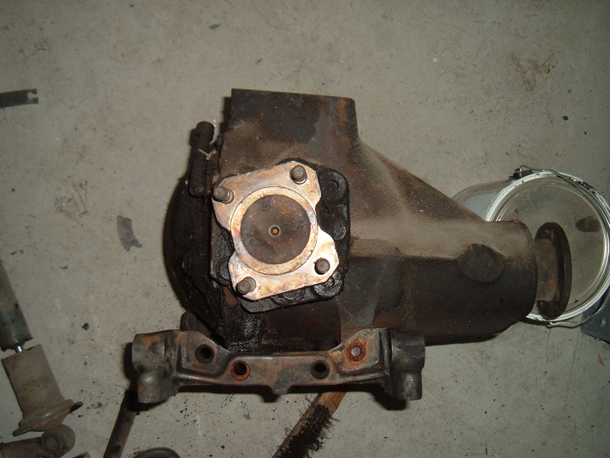
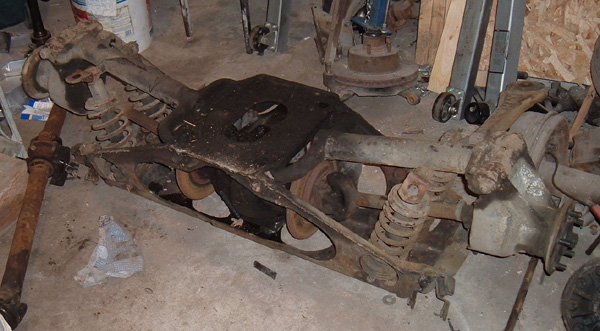
In
the first picture I have the XJ6 bracket on the diff and you can see
how it is parallel with the pinion but misaligned with the top of the
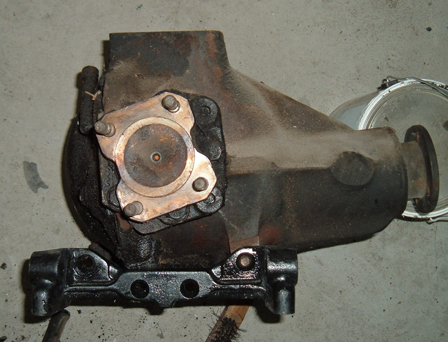
differential. In the second picture I have the XKE bracket on the
diff and you can see how it is parallel with the top mounting bracket,
but the pinion is angled up, just the way I wanted it!!
Finding the correct angled side brackets: I have found several sources for these brackets, but in finding them I discovered that the jaguar community over the years has used them somewhat interchangeably and some suppliers didn't even know there was a difference. The easiest way to communicate the difference was to have the seller measure the distance between the center holes center to center. The XJ6 bracket is about 2 & 7/8" where as the XKE bracket is about 2" I can only assume that the 3.8S bracket would have holes that are half way in between these two measurements since the angle is half way in between. I discovered another huge advantage to these XKE brackets, everything lines up!!! The centerline between the top mounting holes, the drive axles, and the middle of the side brackets all line up. When I first drew up my upper mount using the XJ6 side brackets I had to take in to account the angles and off sets so that my crossbars lined up with my wishbone shock mounts and so the axle lined up with the middle of the wheel well allowing for some backward travel during suspension compression. With the new brackets all that is gone. I simply center the cross bars over the center of the wheel well, and then center the 4 mounting holes in relation to the cross bars and I am done!!! In page VIII I will with another major issue that came up and do the first full mock up where the entire IRS is mounted under the car.
|