In
1964, Ford Motor Company decided to
wedge a 427 big block into a
Fairlane. It was an engineering nightmare but when they were
done,
the Thunderbolt was born. Many modifications were made to
this car
including frame, suspension, and, most importantly, true ram air.
Many people have
"ram air "
on their cars, or at least they think they
do. A hood scoop is a wonderful way to provide cool fresh air
to
a motor, however, even if you are cruising down the road at 80+MPH,
there is
not enough air pressure at the scoop to force air into the
motor.
The problem is that air pressure is created in front of the
car.
As the air is pushed out of the way, it is forced up, down ,
and
to the sides. The upward motion of the air dissipating off
the
front of the car redirects any forward air that would be going into
your hood
scoop, up and over the car. Think of it like a bug deflector,
but instead of pushing bugs up and over the car, it is air flow. I
received this quote in an email:
"I have
experience in the "Bug
Deflector" idea. I have an '89 Mustang with a Cervini's Ram
Air
hood. I spent probably an extra $400 for the ram air
kit.
From 0-30 MPH, there is very little difference and could be slightly
slower. From 30-80, you can feel a SLIGHT bit of
increase.
At 80+, there is a tremendous bog due to lack of air. I left
the
kit functional for only about a month. Since then, it's
taking up
storage space in the basement." Scott
Fouts
As illustrated, this means
little-to-no air pressure at the scoop. There is a
solution, however, tubes can be run from the front of the car to a
sealed air cleaner holder, which will give you true ram air.
The
best part is, this is something you can build at home with very little
time and money.
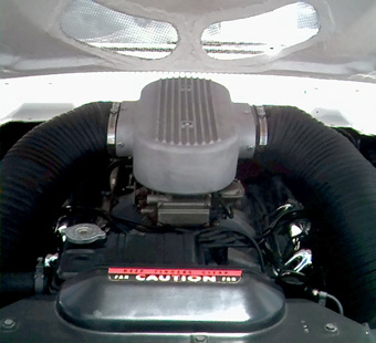
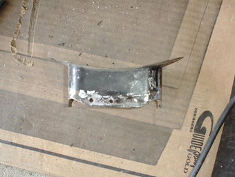
This
is what the original Ford ram air set up looks like on the Thunderbolt.
As
you can see, one set of
headlights was removed and replaced with the air inlets
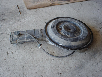
This is a
stock Ford air
cleaner. This part was relatively unchanged from the early
70s
until it was no longer needed when EFI replaced the carb. For
the
most part, all makes and models of Ford vehicles had the same
basic system.
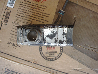
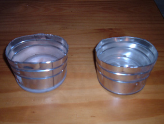
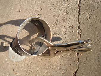
The first
step is to
remove the air inlet snout. There are either two bolts or two
rivets
holding it to the air cleaner housing. I found that drilling
out
the rivets works very well. If you want a dual snorkel system
you
will need two of these.
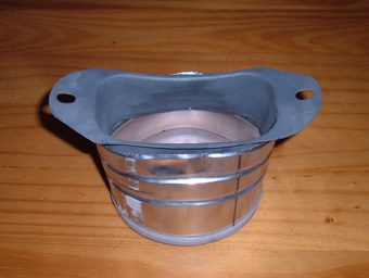
This is the
only piece of
the stock air inlet snout that will be used in the ram air
system.
There are three spot welds attaching this to the inlet snout on both
the
top and bottom. Once drilled out, this piece slides right out
off
of the end. After I got all the pieces apart, I blasted them
in
my
blast cabinet to get everything clean and ready for
reassembly.
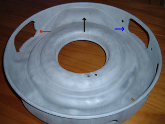
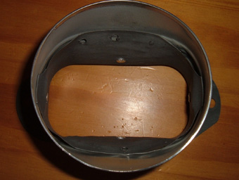
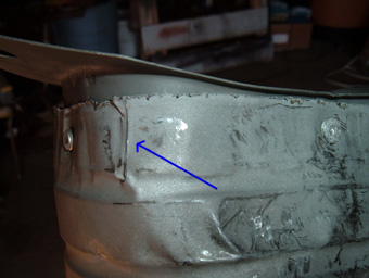
The blue
arrow points to
the factory air inlet hole, and the red arrow points to the air inlet
hole that I cut into the air cleaner housing. The new hole is
a
mirror image of the factory one, including tabs to help
center
the
inlet pieces. The new hole is placed on the other side
of
the hump (pointed out by the black arrow) that
allows the
air cleaner housing to fit over the distributor
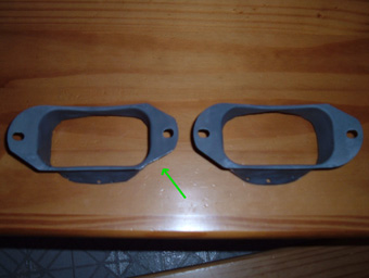
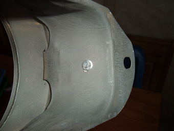
Two things
needed to be
done to the air inlets. First, I cut the rounded
tab off of
one inlet so that it didn't hang down past the air cleaner
housing. This is shown by the green arrow. The second thing
that
needed to be done was the inlets needed to be flared out to a more
round shape. This is better illustrated below.
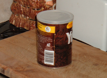
Believe it or
not this is
a vital piece of the ram set up, I know
it seems
hokey, but you will see that this will work very well. This
is
the small size coffee can. It is a 4 inch diameter
which is
a perfect fit to the inlet tubes. It is also flexible enough
that
is can be shaped, but the thicker ring on the top and bottom hold the 4
inch round shape.
Once you have
removed the
coffee and the label, the can needs to be cut in half right in the
middle. It then needs to be elongated to match the shape
of
the air inlets.
This picture
illustrates
the inlet placed into one half of the coffee can.
It takes
a little bending and shaping to get it in but it is a fairly good
fit. The gaps will be dealt with later.
This inside
shot shows how
the inlet was bent to match the round shape of the coffee
can. It also shows how the two parts work together
to make
a semi smooth transition from round to rectangular.
This
transition will be smoothed out in later steps.
I used
poprivits to attach
the coffee can to the inlet. There are 4 of them, one on each
side
of the inlet. One thing that is very important is
that I
installed the poprivits from the inside out so that the smooth side is
on the inside. It is important that all surfaces be
as
smooth
as possible.
Before I
poprivited the
can onto the inlet, I made 4 cuts on each corner of the can all the way
to the first rib of the can. This allows the metal to move
more
freely as the can is smoothed onto the inlet. Note:
slight
forming can be done before poprivits are installed, but most of it
should be done after.
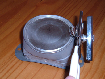
These
vice-grips were used
to form the can and the inlet together. I used a
tapping
motion, as if removing a dent, to massage the can
metal up
against the inlet walls. I also used pressure from my
fingers,
and light hammer blows to form the two together. It doesn't
need
to
be perfect, just a small amount of gap.
One thing I
learned was
that the bottom half of the can held its round shape during forming
better than the top half, because the
bottom metal seal had not been removed. One thing I would
recommend is that
you waste the coffee by cutting the can in half with out taking the
coffee out so that the top and
bottom seal can be intact during shaping. After shaping a can
opener can be used to remove the seals just as if opening a normal can.
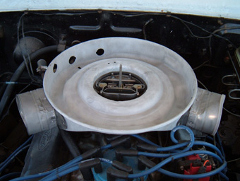
This is a
test-fit
to make sure everything is fitting the way it needs to. As
you
can see, the air cleaner is really starting to take shape. On
the
next page I will show you how to seal everything up and test
it
for leaks, I will also discuss why I used 4" tubing, and why I am not
concerned about some flow restriction caused by using an original air
cleaner.
Before
we
continue with the
construction of our ram air system, I first want to address a few
issues. The general thought with most things in
life is
that
bigger is better. With this thought, one might feel
that
two
4 inch inlets won't be big enough or, worse yet,
that
the 3.5 by 2.5 area of the snout on each snorkel
won't flow
enough air, but if we do the math we see there is
plenty.
For those of you who think "math" belongs with the list of other 4
letter
words that should not be said, I completely understand, please skip to
the paragraph entitled Why it Works, but for those who want to see how
it figures out, please read on.
The math:
The facts for my
calculations:
the
opening area of one
inlet is 8.75 Square inches (3.5 * 2.5)
one square foot is =
144 square inches.
number
of inlets =2
Speed 60 MPH or 1 Mile (5280 feet) Per Minute
motor
size = 302
RPM @
60 MPH approximately
3000. I got an average if 2560 so I rounded up
So if we take 8.75 and
divide it by 144 we
get .061 square
feet. Multiplying .061 times the distance traveled
per
minute, 5280
feet, we get a Cubic Feet per Minute flow rating of
320.83. That
figure is for one inlet but in this case we have 2 so when you multiply
320.83 * 2 we get 641.67 CFM. The calculations for
figuring the
correct carb cfm for any motor at any given RPM are as follows. CID *
RPM / 3456. If we plug in the remaining
numbers, 302 * 3000 / 3456
= 262.15 CFM draw from a 302 at 60 MPH and 3000
RPM. To put
it another
way, the ram air setup is supplying 2.45 times the CFM required by our
motor. Now all of these calculations were done assuming that
flow
is
reduced to the most restrictive point. In reality, that is
not
the
way it works. A short restrictive point will reduce flow, but not to a
point equal to the most restrictive points area. If you do
all
the same calculations for the two inlet tubes with a 4 inch diameter
each (the least restrictive point in this system) we get a CFM of
921.53 or 3.5
times the CFM requirement. Our actual flow rate would fall
somewhere in between 921.53 CFM and 641.67 CFM. There are too
many
variables like tube flow rate, air filter restrictions, and
air
cleaner housing shape, to easily get it more accurate than a range of
potential CFM. An average of the high and low is probably a fairly
accurate approximation of the actual CFM flow of our system.
781.6
CFM at 60 MPH almost 3 times the motors CFM requirements.
Why it
Works:
As
is addressed in my
page"Efficiency
-vs-
Volume Increases", some of the
power produced by a motor is
used by
the motor to run. It takes horsepower to drive the water
pump,
fuel pump, and oil pump. The same thing applies to drawing
fuel
and air into a motor. With every intake stroke, horsepower
produced by the motor is used to draw fuel air mix into the
motor. By forcing the air in rather than drawing it in we are
eliminating the use of that horsepower and reclaiming it at the
flywheel. Those are free horses with no penalty to fuel
economy. Another benefit is that the air forced in
is
cooler than the normal air under the hood. Cooler air is denser and
provides more air in the cylinder with every intake stroke and improves
the % burn (also addressed in"Efficiency
-vs-
Volume Increases"). The last benefit
is boost, up to 2 pounds of boost can be
achieved at 90 + MPH. Don't get me wrong, Ram Air
is no
replacement for a supercharger or turbo charge, but still gives a small
amount of boost that wasn't there before. The majority of the
performance gains afforded by ram air come from large amounts of cool
air entering the motor with no effort from the motor.
So
here it
is. It
fits well and the tubes will clear the parts of the motor. It
is
now time to make it air tight, and plumb the air tubes into the front
of our car.
We are now
going to use
plastic filler and fiberglass to seal all the holes on the air filter,
strengthen the coffee can area, and smooth out the transition from
round to rectangular.
Pictures
and step-by-step instructions still to come.
Last modified 03/01/05
Disclaimer on Daze Tech Tips
I am not an expert
in this field. I have performed these modifications myself with very
good results. I am passing along restoration and
performance tips for the purpose of education. If you are
concerned about reliability or safety issues, I do not recommend that
you or any other individual perform these changes or attempt to modify
your cars from stock configuration except under your own
volition. I do not assume nor accept any liability for the
use of
this
information or how it is applied.