 |

"I heard rumors that the main parts of the Salisbury differential and the Dana 44 interchanged.... The problem I was having was finding specific info on the subject such as part numbers or the exact changes that needed to made." And
finally an update to this web page:
Page IV of my Jaguar IRS project has been a long time coming. Over the last year, I had to put the project on hold as I had another car that needed my attention, but now that car is basically finished and I have been able to get back to the Jaguar IRS install. I hope that subsequent pages in this series will not take as long to be published as I know there are many people interested to see how the story ends.
The information on this web
site
gave me everything I needed and
confirmed the reality and “best kept secret” that
the main internal
parts used in a standard Dana 44, carrier as well as ring and pinion,
can easily be used in a Salisbury differential providing you get the
correct bearings, seals and other small parts. In many ways, the
Salisbury differential and the Dana 44 can be compared to the Ford 302
and the Ford 289, almost the same, but there are a few differences that
need to be addressed when interchanging parts.
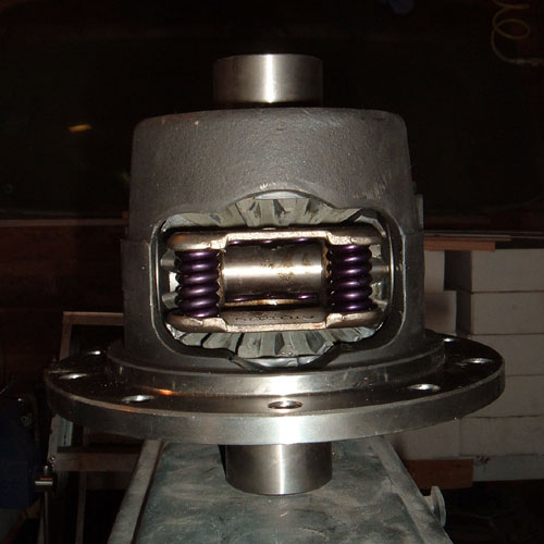
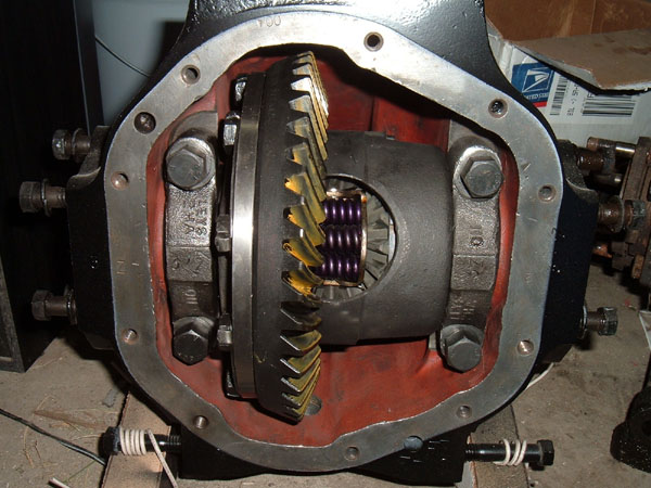
In the case of the differential rebuild for my unit, I wanted to replace the Salisbury open carrier with an Auburn Gear pro series powerlock differential, but still retain the original Salisbury ring and pinion due to the 3.54:1 gearing. I am a competent mechanic and have the tools and basic skills to tackle many types of rebuilds, however, having never worked with a Dana 44 or Salisbury type differential, I did farm out the rebuild of this unit. NOTE if you have never rebuilt a rear end or similar part such as a transmission, I do not recommend starting with this unit.
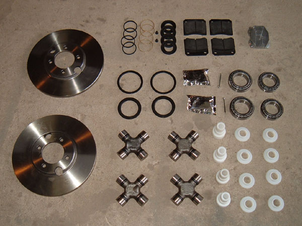
To save labor costs, prior to farming out the rebuild, I did all the legwork on getting the correct parts and pieces for a rebuild kit and brought them in to the rebuilder with the differential. I also provided the rebuilder with a copy of the Jaguar shop manual information pertaining to the differential unit. You can use Dana 44 gears, however, if you use them with the carrier from the Salisbury differential, the bolt holes on the carrier for attaching it to the ring gear will need to be sleeved or shoulder bolts will need to be used because the holes in the Salisbury carrier are 7/16" and the holes on the Dana 44 ring gears are 3/8". Since I chose to replace the Salisbury carrier with an Auburn Gear power lock differential, but still use the original Salisbury ring and pinion, the holes on my Auburn Gear carrier had to be punched out to 7/16". NOTE when ordering a Dana 44 carrier, make sure you get the correct spline count. The Salisbury differential has a spline count of 19, but the Dana 44 comes in both 19 and 30 spline. Also, depending on the ring and pinion ratio you choose to use, there are two different configurations of carriers available. In other words, one carrier configuration is used for ratios up to 3.73:1 and a different carrier configuration is used for ratios of 3.92:1 and above. NOTE 04/09/10 It was recently brought to my attention by Sedat Yalcin that the above information only applies to Dana 44 carriers. If you are using the original Jaguar carrier you need to be aware of three different carriers. The 2.88:1 carrier will only work with 2.88:1 ring and pinion. If you have a 2.88:1 carrier and want a lower ratio you must change the carrier or buy a custom "THICK" gear. After getting this information I confirmed it by contacting Mike at CWI and he added that Jaguar made there break between low and midrange ratio at 3.54:1 and 3.76:1. The important thing to keep in mind when deciding weather you need the parts set up for high or low ratios (excluding the 2.88:1) is not weather the carrier is Jaguar or Dana 44 but weather the ring and pinion are Jaguar or Dana 44. If the ring and pinion is Jaguar, regardless of weather the carrier is Jaguar or Dana the break in ratios is between 3.54:1 and 3.76:1. But in reverse if the ring and pinion is Dana, regardless of weather the carrier is Jaguar or Dana the break in ratios is between 3.73:1 and 3.92:1. The carrier bearings are another one of the things different between the two types of differential. Both use the same bearing race, but the I.D. of the bearings is different to accommodate the different sized bearing mounting locations on the Dana 44 or Salisbury carriers respectively. Pinion bearings are also different depending on whether you choose to use the Salisbury or Dana 44 ring and pinion. NOTE you must use matched ring and pinion sets, in other words, do not try and use a Dana 44 ring gear with the Salisbury pinion gear or vice versa. A list of part numbers for a full Dana 44 rebuild, a full Salisbury rebuild and a combo rebuild are listed below. NOTE the Dana 44 #s are in relation to installing Dana 44 parts on the Salisbury differential and may or may not apply to an actual Dana 44. I ordered most of my parts from Reider Racing, because, after much research, they had the best prices but most importantly they were extremely helpful when I talked to them on the phone. http://www.reiderracing.com/ If you use Dana 44 ring and pinion, your pinion bearings will be different from the Salisbury pinion bearings. Also, the original Salisbury input flange that bolts up to the drive line yoke will not fit on the Dana 44 pinion gear, and a Dana 44 output yoke will be needed. Make sure you think through which way you want to go. By upgrading everything to Dana 44, you make things simpler for future repairs, however, a full rebuild is required and all the parts can be expensive. Also, if you retain the Salisbury ring and pinion but upgrade to a Dana 44 carrier, note that once the holes are punched out in the carrier, sleeving them to later accommodate a Dana 44 ring and pinion set may be difficult and time consuming. Differential rebuild part numbers:
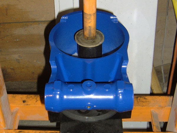
RR# = Reider Racing part # S# = Spicer part # CWI = Concourse West Industries When I got the
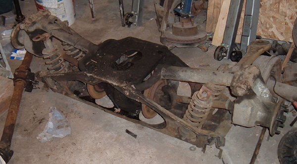
rebuilt unit back from
the rebuilder, he told me the rebuild was easy and that there were no
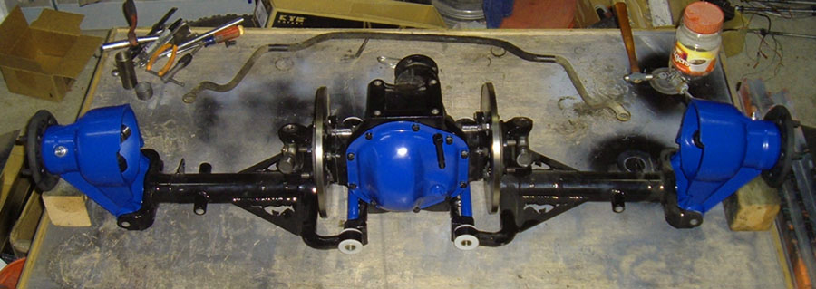
problems setting it up. The unit needed a fresh
coat of
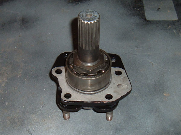
paint and once I did that it was ready for use with the exception of
needing the drive shafts rebuilt and installed which was the next task
in the rebuild process.
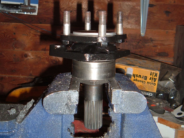
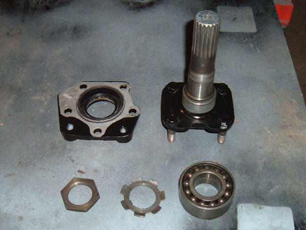
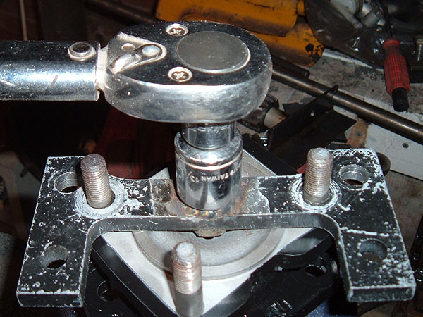
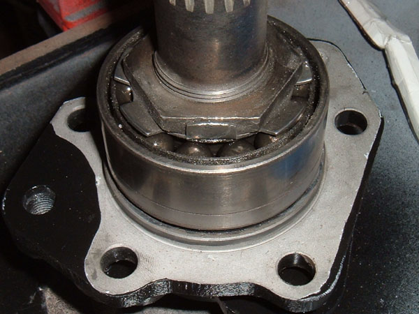
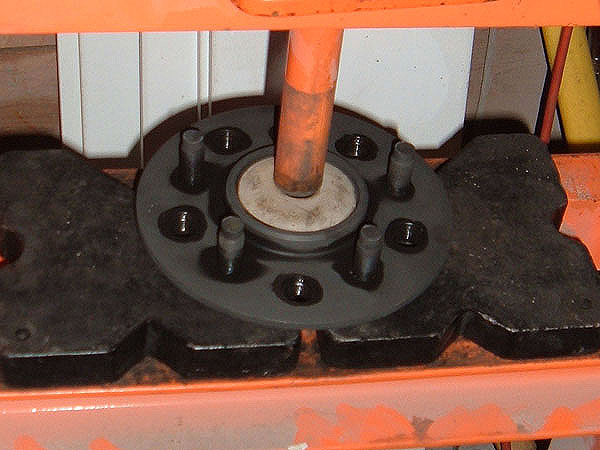
The good news and the bad news about drive shafts: Jaguar produced two different styles of drive shafts on the XJ series cars. The series I Jaguar 1969-1973 uses a ball bearing on the drive shaft. These drive shaft bearings are not made any more so replacing them is not an option. The good news is that since the weight of the vehicle is not on the shaft bearings as it is on the wheel bearings, there is little to no pressure on them so, as long as the differential is properly maintained, the bearings can last for hundreds of thousands of miles. The drive shafts are very easy to disassemble so that the bearings can be inspected and so that the seals can be replaced. Keep in mind that trying to replace the drive shaft seals after the unit has been installed in your car will be a major undertaking since getting to them requires removing the unit from the car and taking much of it apart, so I recommend replacing the seals before the unit is ever installed in the car. In 74, Jaguar upgraded to a double taper bearing. This is a much stronger design, however, they are set up with a crush sleeve between the bearings to properly set the bearing preload. This means that rebuilding them is a little more challenging. Since the early type bearings are no longer being made, the only option, if you want new bearings, is to replace the entire drive shaft by scavenging a set from a newer series II or III Jaguar. The differential I am using came from a 72 XJ6, so it came with the ball bearing type drive shafts. I purchased a set of series III drive shafts from David Boger at EveryDay XJ with the intent to “upgrade”. Since I already had the seals I needed to rebuild the older drive shafts and the bearings seemed to be in good shape, I decided to set the newer drive shafts on a shelf and run the original ones that came with my differential. Rebuilding these early drive shafts is relatively simple. The first thing I had to do was bend down the retaining tab on the washer under the nut so that I could remove the retaining nut. Not having a wrench large enough to fit on the retaining nut, I found the easiest way to remove it was to place the drive shaft upside-down in my vise with the retaining nut in its jaws and then place a steel rod through the drive shaft studs and use the steel to turn the drive shafts. Once the nut was free, I set the entire drive shaft in a tub and began to remove the bearing parts. Each bearing comes completely apart and the balls come loose from the race and the bearing cage, so the tub is there to catch the steel balls should things fall apart. The individual bearings need to be inspected for flat spots or wear rings, also the bearing retainers need to be inspected for cracks.
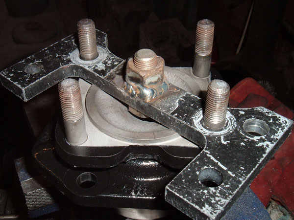
Once the bearing is off, the caliper bracket was removed from the drive shaft and I had access to the seal in the caliper bracket, which I drove out with a punch. From there the parts were cleaned and painted and the bearings were reassembled. Sometimes getting the balls back in the bearing retainer and then getting the bearing retainer back in the race can be a challenge but by adding a dob of grease to each ball as you put stuff back together it will act kind of like a temporary glue and make the process much easier. From there the process was the same as disassembly only in reverse. I installed a new seal into the caliper bracket, which was then installed on the drive shaft. I then reinstalled the bearings, followed by the locking ring and the nut. As I was tightening the nut, I wanted to make sure I torqued it to factory specs. Unfortunately, the length of the axle prohibits you from fitting a socket over the nut and consequently makes using the torque wrench a problem. To overcome this I placed the drive shaft in my vise as I had done to remove the retaining nut and placed (Homemade Tool #5) over two of the drive shaft studs. This tool is simply a piece of scrap steel with two holes drilled out for the studs and a lugnut welded to the middle. With the tool installed, I was then able to put a socket on the lugnut and use my torque wrench to correctly tighten the drive shaft retaining nut. Once things were torqued to factory specs, I bent a tab up on the locking ring to secure the nut.
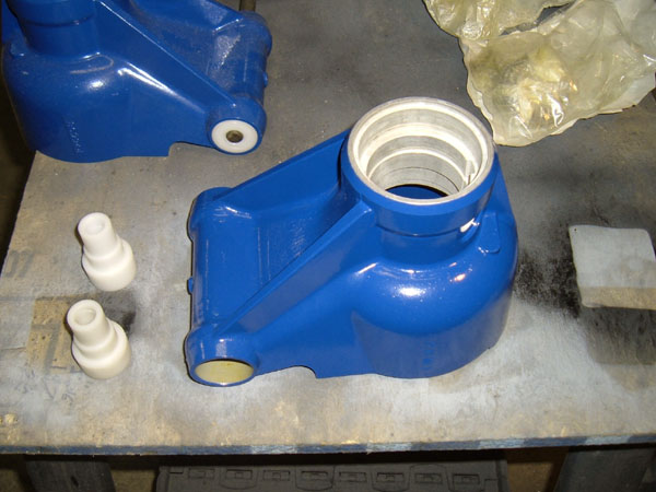
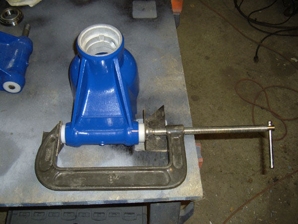
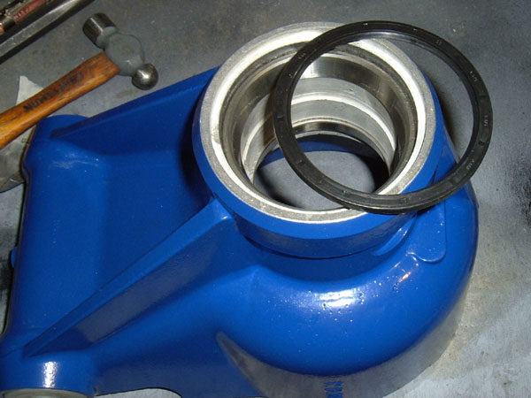
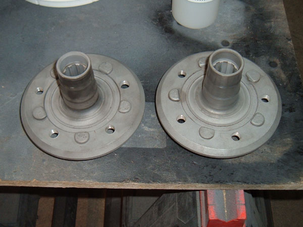
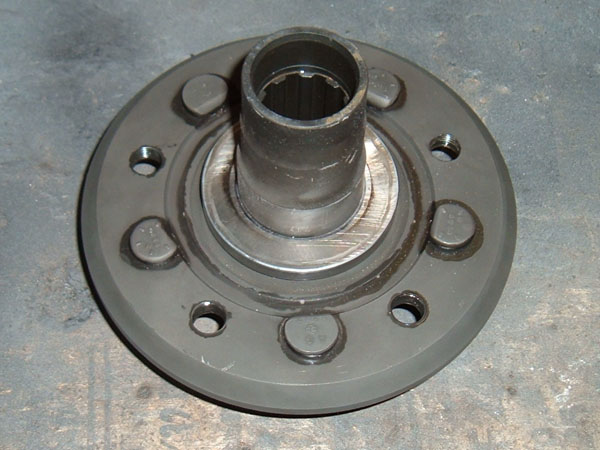
Installing the drive shafts into the differential: Prior to installing the drive shafts, the o-ring seals need to be examined. In the case of the 74 and up drive shafts, the o-rings are available. They fit onto the body of the caliper bracket and can be easily replaced. On the 69-73 units, the o-rings are inside a grove in the differential housing. These o-rings are no longer being made and the original ones will need to be “revitalized” and extra precautions will need to be taken to insure there are no leaks. To revitalize the o-rings, I soaked them in PineSol. Believe it or not, this is a really good way to soften old rubber and I have used it many times on rubber in far worse shape than that of these o-rings. Even with the o-ring “revitalized”, I still wanted to make sure things sealed properly so, just prior to the final install of the drive shafts, I put a thin layer of RTV around the base of caliper bracket where it meets the differential housing. There are shims that need to be placed between the caliper bracket of the drive shaft and the differential housing and, when the differential was originally disassembled, the number of shims/thickness should have been noted so that that they can be put back in their original position. I failed to do this during disassembly so, to determine the thickness, I installed the drive shafts without the shims and hand tightened all 5 bolts on the caliper brackets. I then used a feeler gauge to find out what thickness was required to go between the housing and the flange. Now knowing the thickness needed, I used my digital calipers to measure the shims and stack together enough to achieve the correct thickness. The shims and drive shafts were then installed on the differential and the bolts were torqued down. Rebuilding the hubs: When I pulled my hubs apart, I thought about polishing up the hubs to make for a nice finish. After several hours on one hub with little to show for it, I decided it was more labor than I had time for. A trip to the powder coater was the next best solution and the results are beautiful. When it comes to rebuilding the hubs, you need to keep in mind that there are lots of little pieces in the hubs, especially on the bottom where the lower control arms connect to the hub as you can see in the pictures on page II from when I tore them down. All these little pieces are there for the main purpose of properly setting the preload on the tapered roller bearings there in the lower part of the hub. Tapered bearing always need to be set up correctly with a specific amount of preload since the bearings will loosen up with use, but too much preload and the bearing will bind in the race and, with use, overheat and fail. If enough preload is not put on the bearings, they will not be held in the correct position in their corresponding races and will wear out prematurely. The window for correctly setting the preload is small, as in thousands of an inch, and for this reason many suggest that you have the hubs rebuilt by a professional. With a good shop manual and some special measuring tools, someone with a little experience setting up tapered bearings can set up the bearings on the lower part of the hub themselves, but this is not a task for a novice. There is, however, another option. The rebuild kit I purchased from CWI came with UHMW bushings that replace all the parts in the lower section of the hub, including the bearings. The beauty of this set up is all you need to do is install the bushings and you are done. The bushings will last as long, if not longer, than the bearings and don’t need any maintenance or grease. To install my bushings, I inserted them into the hub as far as I could by hand and then used a C-clamp to press them in the rest of the way. Once they were in, I took a small hammer and tapped them lightly, just to make sure they were fully seated. With the bushings in, I turned my attention to the stub axle bearings and seals.
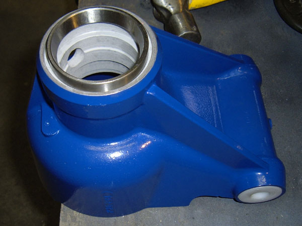
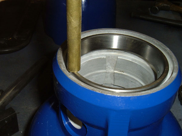
The first step in setting up the stub axle bearings was to install the bearing races. The two bearings in each hub are different sizes so knowing which bearing goes where is fairly straightforward. The races are installed like any other. I always start mine with a rubber or plastic mallet. Once I have them started, I use a small 3 oz hammer and a brass punch to slowly drive the races into the hubs. NOTE the hub is aluminum which is even softer than the steel races and brass punch so be careful to slowly drive the races in, moving the punch all around the top edge of the race to keep the race even as it goes in and make sure the brass punch is on the race and not any part of the aluminum when you strike it with the hammer. It is also important to make sure the hammer blows are light. Tapping in the races, when done correctly, should take many hammer taps and some time. When installing a race it is good to use your ears to help you know when the race is seated properly. The sound of the hammer blows will change from a thud to more of a ringing sound when the race and the hub body are in full contact. With the races installed the outer grease seal can be installed. I was able to press mine in with my fingers. NOTE the outer seal can be installed into the hub but the inner seal cannot be installed until the wheel flange and bearings have been installed.
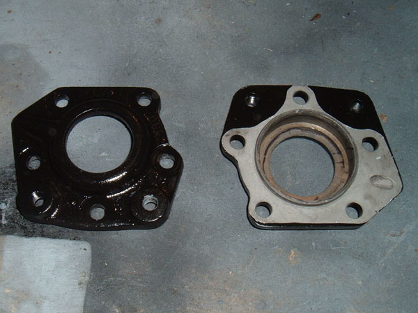
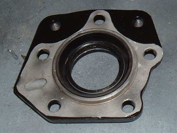
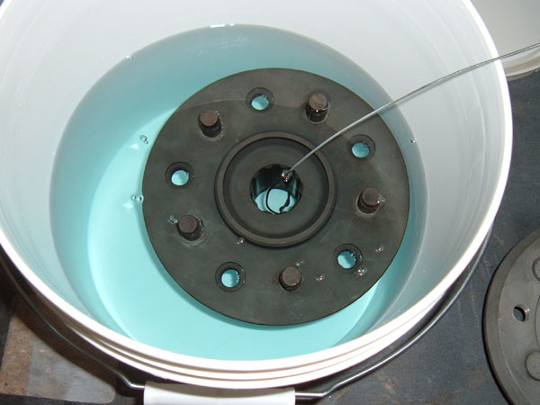
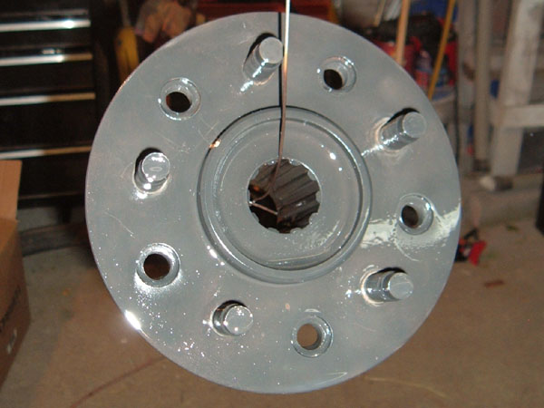
The wheel flanges on my unit were basically the only external parts that I did not powder coat or paint. Powder coating or painting can distort and/or flake off when used between surfaces held together with torqued fasteners such as the wheel-to-wheel flange connection. As the coating compresses or flakes off, this can cause the tension holding the two surfaces together to decrease and cause the torqued fasteners to loosen. Not being able to use paint or powder coat the steel is a problem, as the wheel flange will rust. I chose to deal with this situation in the same way Jaguar did and that is to use black oxide to coat the wheel flanges. This coating adheres to the steel at the molecular level and is only a few molecules thick. Since the compound does not corrode, it makes a nice barrier between the steel and the elements. To apply the black oxide, I bought a kit from Caswell. 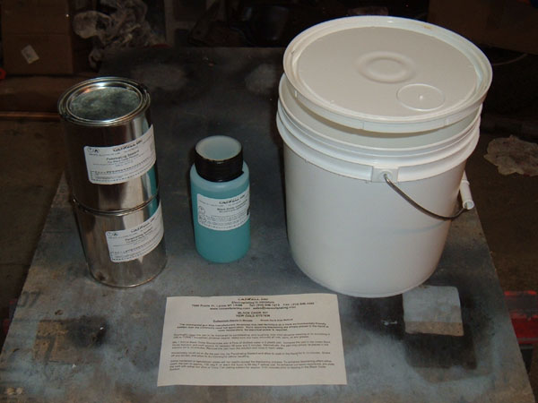 Caswell Black Oxide Kit The directions that came with the Caswell kit were very easy to follow. As directed, I made sure the parts were completely clean and free of all rust and oils. I then mixed the black oxide chemicals with distilled water in the ratio prescribed by the directions. The flanges were then dipped and left to soak for about 10 minutes. During the soaking time, I moved the parts around in the solution to eliminate any bubbles that had formed on the hubs. Once the parts were completely blackened, I removed them from the solution, rinsed them off and covered them with the sealing oil provided with the kit
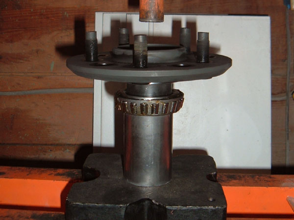
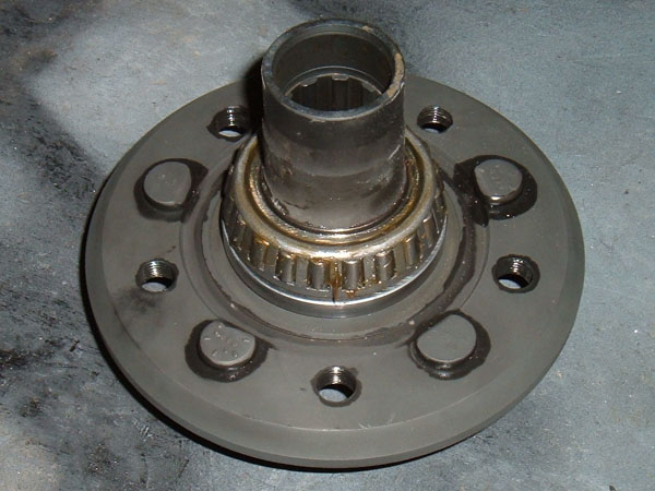
With the wheel flanges protected, I pressed the seal plate onto the flange and then after thoroughly packing the bearing with grease, I pressed it on as well. It is important to make sure the seal plate is installed between the bearing and the flange, as it is the only thing that rides up against the rubber grease seal. With the parts pressed on the flange, I inserted it into the hub and spun the flange to properly seat the bearings. I then pressed the inner bearing, which had also been thoroughly packed with grease, onto the inner shaft of the wheel flange. As it was being pressed on, I rotated the hub body back and forth in an attempt to make sure the bearing was not too tight, in other words with it installed you want there to be a little play between the wheel flange and the hub. When I first pressed the inner bearings onto one of my hubs, I pressed it a little too far and had to back the bearing off. To do this, I simply placed the hub in my lap between my legs and used a large punch and a light hammer and tapped on the inside end of the flange, driving the flange out of the hub just enough to loosen up the bearings.Once the inner bearing was installed, I then pressed in the inner seal with my fingers.
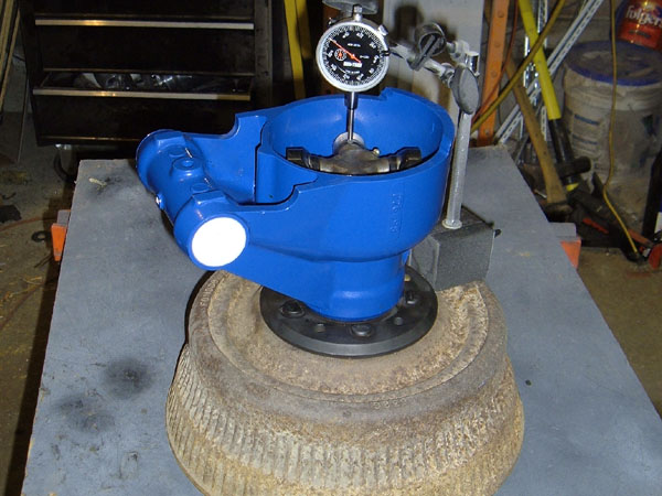
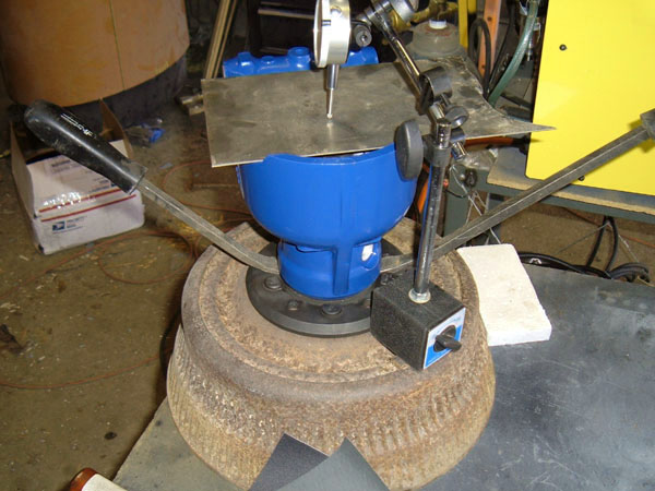
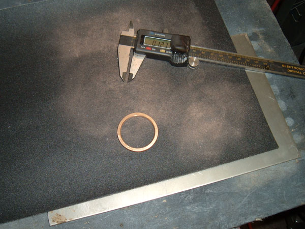
I am about to cover one of the most important steps of rebuilding the hub, which involves correctly shimming the stub axles, but before I do, I want to address a potential issue that I learned about that deals with the possible failure of the stub axles. I found this information on Jag Lovers Forum and it turns out that, in more than one case, the nose of some stub axles have sheared off, allowing the stub axle to separate from the hub. Since the half shaft and stub axle serve as the UCA, if the stub axle were to separate from the hub, the hub would no longer be held in two places and the wheel will probably no longer stay perpendicular to the road. If this were to happen while driving the car, the results could be catastrophic. Alarmed by this possibility, I began to extensively research this issue and learned several things. Summation of problem factors and causes: 1. The sharp cut of the threads creates a natural stress point. 2. The sudden increase in diameter from threaded to splined section increases shear forces at the base of the threads. 3. Failure to correctly assemble the hub WILL increase the chance of sheering of the threaded end. 4. Unknown past damage to the hub parts, such as that caused by an accident, will also increase the chance of sheering of the threaded end. 5. Older parts are made of mildly lesser materials so, in theory, a stub axle from a newer IRS unit should be stronger than that of parts from an older IRS unit. 6. Lack of routine maintenance significantly increases risk. Solutions: 1. To insure that you have a quality used stub axle, have the base of the treads magnofluxed to detect existing micro cracks, or at least use a crack testing solution. It cost me $20.00 to have a local machine shop test my stub axles. This is cheap insurance to insure the parts I am using will function for thousands of miles to come. 2. ASSEMBLE THE UNITS CORRECTLY!! My research found this to be the most important factor in dealing with this issue. I. Use locktite !! II. Measure and shim the stub axle for correct end-float III. Torque down castle nut to factory specs IV. Make sure the stub axle does not bottom out on the washer and castle nut 3. Routine maintenance, I was amazed when I first looked at the maintenance schedule of the Jaguar IRS unit and how much needs to be checked on a mildly regular basis (every 6000 to 10,000 miles depending on the parts). 4. In relation to point 3, if the bearings in the hub are worn out and the shaft has too much end-float, the side-to-side motion will work harden the threaded base on the stub axle, causing it to crystallize and increasing the chance it will sheer off. 5. Be one with the car. Be aware of what the car is doing, how it is handling, and how it sounds. If something changes, find out why. 6. Cutting a small rounded stress reliever (by a qualified machinist) especially in relation to the sharp grooves at the base of the threads may be a viable preventive solution. I, however, chose not to do this as I knew that the stub axles I was using didn’t have any cracks and that the hubs would be set up correctly. 7. Newer parts from say a series III Jaguar, both hub and stub axle are more likely to be stronger than that of the corresponding parts from a series I Jaguar. 8. Do not abuse the suspension. If you drive hard and fast over rough roads all the time, then know the life of the parts will be reduced and routing maintenance needs to be increased. I believe in the concept of knowing all the facts so as to make an educated, informed decision, and with that in mind, I wanted to address the potential issue mentioned above. I also wanted to use this information to stress the importance of correctly setting up the hubs. Keep in mind that just because there is a chance this could happen, it is not likely that it will, especially if the solutions above are heeded. Lets face it, the side of the road is not littered with Jaguars that have sheared off their stub axle threads, so the actual extent of this issue is minimal under NORMAL conditions and, even though the Jaguar IRS system may have room for improvement, it has proven itself reliable when maintained properly. When installing the stub axles into the hub, the tapered bearings need the correct amount of preload or, as the Jaguar shop manual refers to it, the correct “end float”. To properly set the end float a shim of the correct thickness needs to be placed between the bearing seal plate and the inside end of the wheel flange. The brass ring that came with the hub should be perfect, however, you cannot assume that it is correct and measurements must be taken to insure that everything is set up correctly. A Jaguar shop manual gives complete details on setting the end float but also suggests that you use a special tool. Not having the special tool, I set the end float using the stub axles in place of said tool. To set the end float, I installed the original spacer ring and the seal plate and then slid the stub axle into the hub and installed the corresponding washer and castle nut. I torqued the nut down to 85 foot pounds, but as I did it I rotated the wheel flange to insure the bearings were seating correctly and to make sure I was not over tightening them. NOTE if the shim is too thin, the bearings will be too tight and the flange will become difficult to turn. If the castle nut can be torqued to the proper specs of 85 foot pounds without increasing the drag on the wheel flange, a dial indicator can be used to measure end float. When I set the end float on my hubs, I used an old brake drum to bolt the hub to. This gave me a nice solid base for the hub and provided me a large steel surface where I could attach the magnetic base of my dial indicator. With the dial indicator and base attached to the hub, I adjusted it so that the indicator was centered over the u-joint. I then put a piece of steel over the end of the hub to give the dial something to gauge off of and zeroed the gauge. Pry bars were then placed between the wheel flange and hub, and used to pry the hub upward. As the hub moved, the amount of movement registered on the indicator and was noted. When doing these kinds of measurements, it is important to take many measurements and go with the most common result. On one hub I was getting .002” movement, which is perfect as the shop manual says set end float between .001” and .003”, but on the other hub I was getting .010” of play. Too much play meant that the spacer was too thick, so I removed the hub from the stand and took it apart so that I could get to the shim. Once the shim was out, I used my digital calipers to measure the thickness in half a dozen locations on the ring. This spacer measured out at .127” to .129”, depending on where I took the measurements. I then took a piece of sand paper and laid it out on a flat piece of steel and worked the brass spacer back and forth in an even circular motion, regularly changing my finger position on the ring to insure even removal of material. I also took measurements every few minutes to insure that I did not remove too much material. After about 15 minutes of working the piece I had it down to .124” all the way around the ring and even though I had only removed .005” and probably still needed to remove an additional .003” of material, I reinstalled the part into the hub and set back up the dial indicator to take a second reading. This falls into the concept of “measure twice cut once.” My first measurements indicated that I needed to remove .008” of material but I wanted to double check so that I did not accidentally remove too much material and ruin the spacer. The second round of measurement confirmed that there was still .005” of end float, so I once again took the hub apart and continued working the spacer. I removed an additional .003” of material so that both hubs would be set up with the same amount of end float. I confirmed that the end float was .002” by reassembling everything and measuring a third time.
I was lucky that one of my spacers was perfect and the other was too big. If either of the spacers would have been too thin, as the nut is torqued down, it would work like the press, and push the inner bearing on to far. If this happens, you will not only need to back the inner bearing off of the shaft of the wheel flange a little bit, but you will also need to use a thicker spacer. The technique mentioned above that I used to back the inner bearing off of the wheel flange when I pressed the bearing on to far would work perfectly in this case. Once I had the end float set correctly on both hubs, I dissembled each hub one last time. This was done for two reason, first I needed to remove the stub axle from the hub so that I could attach the half shaft to the stub axle. The second reason for disassembling the hub was so that I could reassemble the units using lock tight which, according to the shop manual, needs to be applied to the splines of the stub axle to help secure it to the wheel flange. Once both of these things were done and the hubs were reassembled, the hub and half shaft assembly was ready to be attached to the full IRS assembly. At this point things can begin to come together. The differential, LCAs, rotors, hubs, and half shafts can all be assembled into one unit. By putting everything together you can begin to get a feel for the dimentions of the fully assembled unit and plans for the fabrication that will need to be done to install it in the car can begin to take place. With everything modified and assembled, this project can now move to the final phase and be installed in the car. In the next article, page V, we will look at the final install. 03/28/17, I wrote the above sentence over 6 years ago and not only is this web series not complete but there is to muce info for page five to be the "final" page.
|