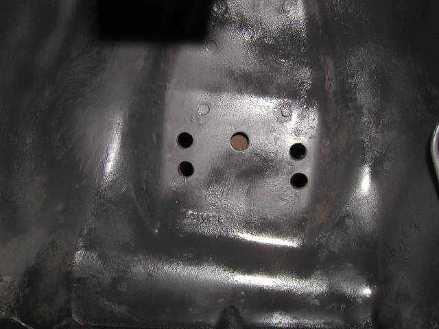
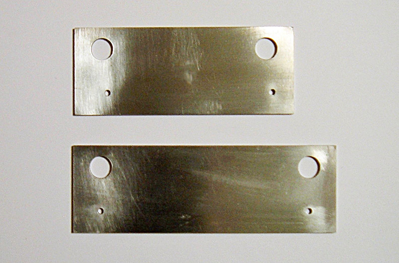
One set of factory holes
at
the top and one set of performance holes at the bottom
A Little
History:
The
Upper Control
Arm, or UCA drop AKA
Shelby Drop, or Arning drop, is one of the more beneficial and easily
the most cost effective suspension upgrade that can be made to a 1965
to 1970 Mustang (also works for Falcons and Cougars). This
simple
act of lowering the mounting point of the upper control arm does more
for the way a classic Mustang handles than many expensive aftermarket
components, and the best part is, other than the cost of your time, the
modification is free, or almost free. Most refer to this
performance upgrade as the Shelby Drop. This is due to the
fact
that the only Mustangs that arrived on the showroom floor with this
modification were the 1965 and early 1966 Shelby models. The
UCA
drop was just one of the many modifications made by Shelby and his crew
to these Mustangs.
Even though most refer to this
modification as
the Shelby drop, in all actuality, if this modification were to be more
accurately named we would call it the Arning Drop. Klaus
Arning
was a Ford suspension engineer who designed this modification to go
with a rear IRS system he had designed for the early Mustang.
Ford decided against the beter camber UCA location on the production
line, however
Arning was able to pass the info for the UCA relocation on to Shelby,
who incorporated it into his cars.
Most
likely the reason ford
located the UCA where they did was to create a camber curve that lent
it self to
understeer. Understeer is a situation where due to slight
traction loss in the front wheels the car does not corner to a degree
of sharpness that the angle of the tires would suggest. It is
common practice among automobile
manufacturers to configure production cars deliberately to have a
slight understeer. If a car understeers slightly,
it tends to be more stable (with drivers of less ability) if a violent
change of direction occurs, thus improving safety. This does not mean
the UCA drop is unsafe, it just means if you are
going to make the steering more responsive and you need to
drive the car with that in mind.
What Does
The UCA
Drop Do?
Three factors make
lowering the UCA an
improvement in handling. First, this modification to the suspension
lowers the center of gravity on the front of the car; second, body roll
is reduced by 7% to 9%; and third, the camber curve is improved.
The
center of
gravity is a geometric
property that relates to any shape, but to keep things simple and
related to the topic of automobiles, it is basically the internal
balancing point from all directions of a car. When you do the UCA drop,
you moderately lower the overall height of the front of the car, which
in turn lowers the center of gravity. Easier understanding
the
application of the center of gravity and how it plays a role in vehicle
stability can be illustrated by looking at the stability changes in a
canoe based on passenger position. If you sit down on the
floor
of a canoe (low center of gravity) then the boat is extremely stable
and nearly impossible to overturn. If you rise up and sit on
the
seats, the canoe becomes noticeably less stable, but still
functional. Finally, if you stand up in a canoe (high center
of
gravity), the boat becomes completely unstable and will most likely
overturn. In the same way the lower the center of gravity is on a
vehicle, the more stable it will be.
Body roll is a
major issue in classic
Mustangs. The structure of the Ford Mustang is what is
referred
to as a unibody design. This means that rather than a stiff
full-length frame, the body is built in such a way that it is
self-supporting. This design is lighter and was more cost
effective for Ford, however, during cornering, especially as you first
enter and begin to exit a corner, the Mustang body flexes and results
in reduced handling accuracy. When you lower the UCA, you
reduce
the leverage that the UCA has on the inner fender/shock tower, which in
turn reduces the force applied to the body during cornering and thus
reduces body roll.
The
biggest
improvements afforded by the
UCA drop come from an improved camber curve. Camber is the
leaning in or out of the tires. The more negative camber you have the
more rubber to road contact you have. If the top of the
wheels
leans in toward the engine compartment, the wheel has negative camber,
whereas if the top of the wheels leans out away from the engine, the
wheel has positive camber. In the same way, during cornering
or
when encountering inconsistencies in the
road, if, due to suspension
travel, the top of the wheels leans in toward the engine compartment,
the wheel has a negative camber curve, or if the top of the wheels
leans out away from the engine, due to suspension travel, then the
wheel has a positive camber curve. The stock camber curve of the
Mustang is positive so, as you corner or if you hit a bump, the top of
the wheels leans out, reducing camber, and thus, reducing rubber to
road contact which results in inferior handling. By
relocating
the UCA, the Mustang camber curve is changed from positive to negative,
which significantly improves handling. Also, another added
benefit of the UCA drop is that the arc of the camber curve is
flattened, which results in a much smaller change in camber during full
range of suspension motion. So, the camber of the wheels stays closer
to the specification it was aligned to during a full range of
suspension motion.
Tools
Needed:
1.
Sharp 1/8” drill bit 2.
Step drill bit or
increasing sizes in normal type bits 3.
17/32” drill bit 4.
1⁄2” deep
socket for shock nuts 5.
Bolt-in Spring
Compressor 6.
3⁄4” wrench
and socket 7.
1⁄2” drill 8.
Floor Jack, jack
stands, 6X6 wooden block 9.
UCA Drop template
Spring
Compressors 101:
Performing the UCA
drop requires
compressing the coil springs. Failure to safely deal with
coil
springs can result in serious injury or even death. There are
three main ways to remove coil springs: external claw type spring
compressor, internal claw type spring compressor, and a bolt-in type
spring compressor. An external claw
type spring compressor
consists of two separate pieces that clamp onto the outside of the coil
spring. As the nuts on the two pieces are tightened down, the
spring is compressed. There are three main issues with this
type
of compressor. First, both sides need to be tightened an
equal
amount and, since each piece has its own tightening nut, this is easier
said than done. Second, this type of compressor REQUIRES that
the
two separate pieces be opposite of each other. Unfortunately,
the
shock towers of a classic Ford do not allow the two pieces to be
positioned completely opposite of each other, which create an unstable
compressed spring. Third, the claws of the compressor are
held to
the spring by tension from the compressed spring. If the
claws
slip, the spring can decompress violently. Many chose to use
this
type of compressor because they are inexpensive and can be purchased
for less than $30.00. The second type of
claw spring
compressor is an internal unit, which has four claws (two at the top
and two at the bottom) that grab an upper and a lower coil of the
spring. One tightening nut pulls the two sets of claws closer
together and compresses the spring. This compressor is much
better for a Mustang then the above mentioned external claw type,
however, it is still not the best option. There are two main
problems with this type of system. First, often times on a
classic Ford, a 3 to 4 inch spacer (usually a piece of pipe) is
required to be positioned between the upper claw assembly and the
tightening head to keep the compressor from bottoming out in the
UCA. Secondly, as with the external claw type, the tension of
the
compressed spring is all that holds the compressor in place and, as
before, if those claws slip, the spring can decompress
violently.
It was this type of compressor that sent me to the emergency room in
June of 2005. After already removing the
passenger’s side spring,
I was working on the driver’s side assembly and had
compressed the
spring and was in the process of removing it when the compressor
slipped, the spring decompressed and pinned my right hand by the three
middle fingers palm side up, between the bottom of the coil spring and
the spring perch. Engaging this type of compressor requires
using
two hands and, of course, I was alone, the garage door was down, my
cell phone was on the passenger’s side fender out of reach
and most of
my tools, at least any that could have been effective in freeing my
hand, were on the floor next to the passenger’s side where I
had
already pulled the suspension apart. All I had within arms
reach
was the 1⁄2” box wrench (no more than 6”
long) that I had just
used to remove the shock. I jammed the wrench in between the
spring and the perch and was able to pry the spring up enough to get
the finger next to my pinkie free. I then pried on the
opposite
side and got my index finger free. To get my middle finger
out, I
pried again with the wrench and pulled as hard as I could with the
trapped arm and got my hand out. To make a long story short, I still
have all my fingers and they still work, however, I occasionally feel
some stiffness in the middle finger joints. I was
lucky!!!!! Needless to say, it is my personal mission to
convince
everyone to use a bolt-in type compressor.
The third type of
spring compressor is
the previously mentioned bolt-in type compressor. This
compressor
bolts to the spring perch and the top of the shock tower, just like a
shock. Once the spring has been compressed, there is no way
for
it to come loose unless you intentionally decompress the
compressor. The “down side” to this type
of compressor is that in
order to completely remove the spring, the UCA needs to be removed to
get the spring out. This adds about 15 minutes to the task of
changing springs, however, that 15 minutes is well worth the improved
safety factor. See my spring
compressor page for details on
how
to build one yourself.
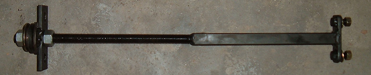
Bolt-in
spring compressor
Performing
the UCA Drop
1.
Remove shocks and Install spring compressor
The first step is
to remove the shock
and replace it with a bolt-in spring compressor. Believe it
or
not, I have found that it is much easier to do much of this part of the
job with the car on the ground. When the car is still on the
ground, the UCA is almost parallel with the ground and, with the UCA in
this position there is easy removal of the shock nuts and the spring
perch nuts. Also, with the car on the ground, the spring
compressor can be just as easily installed and the weight of the car
helps to compress the springs, making the tightening of the compressor
much easier.
2.
Compress spring, Unbolt spring perch from A-arm
As mentioned
above, with the car still
on the ground, compress the springs about 1” to 2”
lower than normal
ride height, then slowly jack up the car. Since the nuts that
hold the spring perch to the UCA have been removed, the spring perch
should pull free of the UCA as the car body rises and the suspension
drops. As the suspension drops, make sure that the brake
hoses
are not supporting the weight of the suspension.
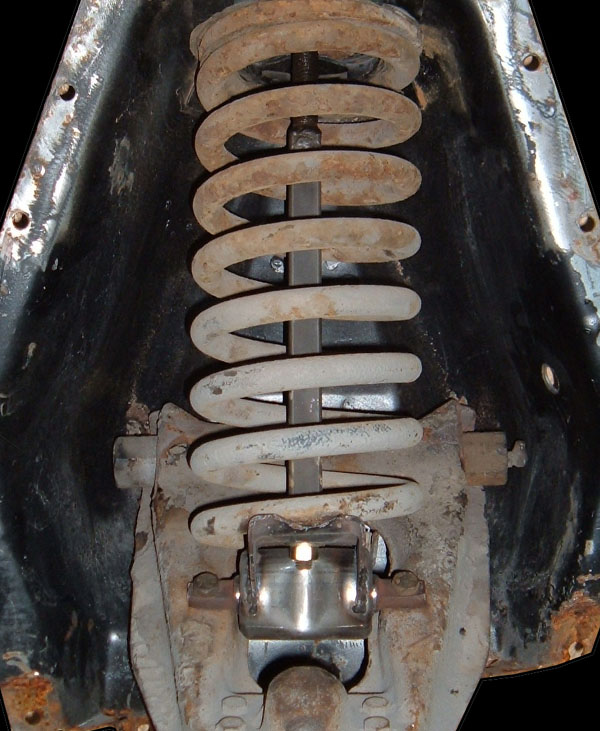
3.
Remove UCA, Support the hub, Save shims, and Inspect UCA
Suspension in stock
configuration
Once you have the
spring perch free of
the UCA, remove the two nuts that hold the UCA to the shock
tower. Before you pull the UCA free of the shock tower, reach
behind and remove any shims (cars before 1967) and keep track of what
shims went where. I always wrap mine with masking tape and
label
them so I know exactly where the suspension settings were prior to the
modification. Also prior to UCA removal, I recommend placing
a 6
X 6 block of wood under the Lower Control Arm, LCA, so that, once the
UCA is removed, the weight of the spindle and brake assembly is not on
the brake hose. Remove the UCA and shift the assembly to the rear of
the car, making sure that there is no undue strain put on previously
mentioned brake hoses. There is no need to remove the UCA
from
the spindle, however, if you have not already done so, this is a good
time to rebuild the
UCA
bushing for improved greaseability and extra
positive caster. At the very least,
you
need to inspect the UCA to ensure it is in reusable condition, as well
as inspect the ball joint and pivot bushing.
4.
Decompress and remove spring
With a bolt-in
type compressor, the
spring perch is bolted to the compressor and holds the compressed
spring in place. That means one could, in theory, perform the
UCA
drop without removing the springs, however, I do not recommend
this. Compressed springs can be dangerous to work with and I
would much rather take the few extra minutes required to decompress the
spring and remove it than to be working in direct contact with a bomb
(I mean compressed spring) waiting to go off. Loosen the
spring
compressor until all spring tension is eliminated, making sure the
spring perch does not catch on the frame rail at the base of the shock
tower, and then remove the tightening nut from the compressor so that
you can drop the spring perch, spring and compressor out of the shock
tower as a unit and set them off to the side.
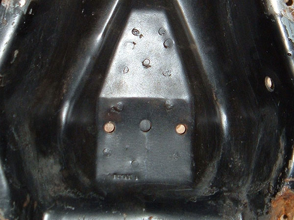
Original holes no
UCA drop holes
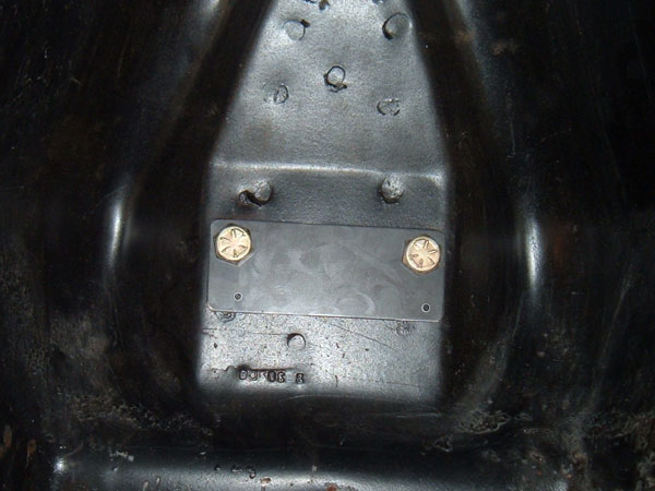
Steel template
bolted into place
5.
Bolt in template The physical
specifications of the UCA
drop for Falcons and Mustangs 1960-1966 are 1” down
perpendicular to
the centerline of the original UCA mounting holes and 1/8”
back along
the centerline of the new holes locations. The physical specifications
of the UCA drop for Falcons, Cougars and Mustangs 1967-1970 are
1” down
perpendicular to the centerline of the original UCA mounting.
A
paper template can be used to drill the new holes, however, for ease
and accuracy, I recommend making or buying a guide template that can be
bolted into place using the original UCA mounting holes, and then used
to drill two 1/8” pilot holes. Metal templates can be
purchased from my For
Sale page. The main advantage of using
a metal template rather than a paper template is that you have the
opportunity to measure the pilot holes to ensure accuracy prior to
drilling in the shock tower. When using a paper template,
said
pilot holes are drilled directly into the shock tower and, if their
location is off, relocating them can be a challenge. The only
time the pilot holes locations would be different than the above
mentioned is if performing an “improved positive caster
drop”. NOTE: if
performing this modification on a car
made before 1967 or if you are performing an improved positive caster
drop, make sure the new holes are located to the rear of the
car.
If you bolt in a steel template backward it will cause you to drill the
pilot holes towards the front of the car.
Information on improving caster through the UCA drop is located
below. Once the 1/8” pilot holes have been drilled,
the template
can be unbolted and used on the other side.
6.
Drill holes 17/32” The steel used to
make the shock towers
of these early Ford cars is probably the hardest steel on the
vehicle. Because of this, I recommend drilling out the holes
one
size at a time, starting with 1/8” and going up no more than
1/16” at a
time, but preferably 1/32” at a time. Using a step
drill bit can
easily facilitate this. The final drill bit size needs to be
17/32” and can be purchased on my For
Sale page. It is well worth it to
purchase the
correct
size drill
bit rather than worbeling the hole out with a 1⁄2”
bit or
increasing the size with a file. The hole needs to be just
bigger
than 1⁄2” so that the UCA can be easily installed
and removed and
also, on the pre-1967 cars, so that the UCA can be moved easily when
installing alignment shims. NOTE: when
drilling
the holes make sure that you are not drilling into any parts in the
engine compartment other than the shock tower. When I did
mine, I
placed a piece of 1/8” plate steel between the shock tower
and my
header tubes to ensure I didn’t puncture them.
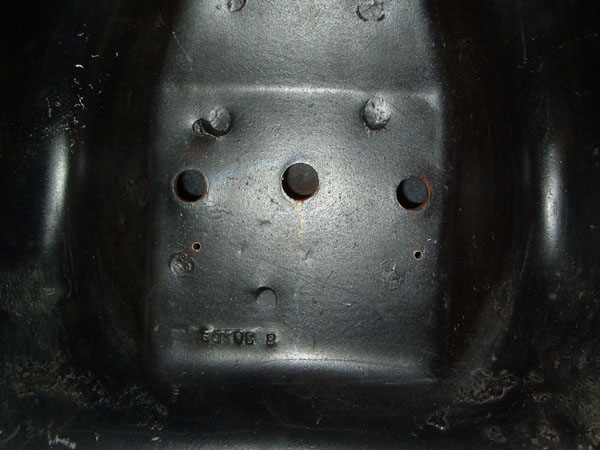
7.
Reinstall spring
Pilot holes ready to be enlarged
Once the new holes
are drilled, it is
time to put everything back together. Start by taking the
spring
compressor, spring perch and coil spring assembly and reinstalling them
back into the shock tower. Once the compressor is back in
place,
install the spring compressor tightening nut and begin to tighten it
down. As you tighten it down, make sure the spring perch
stays
correctly positioned with the spring stop in the back toward the engine
compartment. The spring compressor will need to be tightened
to
the point where the A-arm can be installed.
9.
Inspect suspension stop, Install A-arm including shims Prior to
reinstallation of the UCA, it
is important to make sure that the rubber stops on the under side of
the shock tower are in good shape. If these stops are damaged
or
missing, it is possible for the suspension to travel to an unsafe
position, which can cause ball joint failure. Once stops are
deemed sufficient, install UCA in the new mounting holes and install
the spring perch mounting bolts into the UCA. You
may need
to tighten or loosen the spring compressor just a bit to effectively
position everything. Install the spring perch nuts and the
UCA
nuts, remembering before you tighten the UCA nuts down, take the shims
you removed earlier (pre-1967 cars), remove 1/8” to
1⁄4” of them
(removing the same amount from all four sets) and install them between
the UCA and shock tower in the position they came in. Tighten
down the UCA bolts and spring perch nuts and torque to factory
specs. NOTE: the
rear UCA bolt comes through near a
small metal ridge on the shock tower in the engine
compartment.
Some people tighten the nut down onto the ridge but I personally choose
to grind down one side of a washer and install it between the shock
tower and the nut so the nut doesn’t hit on the ridge. 10.
Install wheel, Lower car, Remove spring compressor, and Install Shock Once you have the
UCA and spring
perch/spring assembly installed and all nuts and bolts have been
torqued to factory specifications, you can install the wheel and lower
the car back down to the ground. As with step 1, removing the
bolt-in spring compressor and installing the shock is much easier with
the full weight of the car on the ground.
11.
Modify other side Once one side has
been modified, repeat
steps 1-10 on the other side. After both sides have been
modified
and are put back together, it is now time for the final step, which is
to have the car aligned.
Having
the car aligned: There are several
things to keep in mind
when having your car aligned. First, factory Ford settings WILL NOT make for a
good handling
car. The original Ford settings were created with tires made
in
the 1960’s in mind and are not the ideal settings to maximize
performance. Second, make sure you trust the alignment
shop. Aligning an early Ford can be very challenging,
especially
with a “shim” type alignment because as you change
either camber or
caster, the other setting is affected. This makes the process
very time consuming and some alignment shops will align the car to
settings easy for them, rather than the setting you
requested. NOTE:
for
best
results, have the alignment shop print out a before and after
specification sheet. Third,
aligning a classic
Ford,
especially a pre-1967 car, is not an exact process and, due to the
effects that changing either camber or caster have on each other, the
alignment shop will need a set of tolerance specifications to align the
car within. The following is a print out that I take to my
alignment shop every time I have my car aligned.
Please align to these specs
“1960-1966
Mustang and Falcon Performance Alignment with or without UCA drop”.
These specifications are in order of
importance.
1.
NO more
than .25 degrees difference between driver’s side and
passenger’s side.
2. +2.0 to +3.5 degrees caster.
NOTE: for cars with Adjustable strut rods. Please attain as
much
caster as possible using the shims (at least 1.5 to 2.0 degrees), and
then use the adjustable strut rods to increase the caster and
make the
sides the same. Also, please note that the caster difference
between the driver’s side and passenger’s side
needs to have no more
.25 degrees difference prior to the adjustment of the strut rods.
3. -.5 to 0 degrees camber. No positive camber,
please. There is no problem having a slight variation from
driver’s side to passenger’s side to account for
the crown in the road.
4. 1/16" to 1/8” toe in
If you run into any problems attaining these specs, please call me
(your phone number here).
Please align to these specs
“1967-1970
Mustang, Falcon & Cougar Performance Alignment with or without UCA
drop”.
These specifications are in order of
importance.
1.
NO more
than .25 degrees difference between driver’s side and
passenger’s side.
2. +2.0 to +3.5 degrees caster.
3. -.5 to 0 degrees camber. No positive camber,
please. There is no problem having a slight variation from
driver’s side to passenger’s side to account for
the crown in the road.
4. 1/16" to 1/8” toe in
If you run into any problems attaining these specs, please call me
(your phone number here).
Once
you have the car aligned, it is time to drive, drive, and drive some
more. You should notice an immediate improvement in the way
the
car handles. As I have said before, the UCA drop is one of
the
single biggest ways to improve the way a Mustang handles and it should
be obvious the first time you take it for a spin
Other
Things To
Consider:
Increased
caster drop
It is
possible to do a UCA drop that improves caster by relocating the UCA
further toward the rear of the car. In the case of both the
1960-1966 drop and the 1967-1970 drop, you should be able to relocate
the holes 1/16” to 1/8” toward the rear of the
car. In a
1960-1966 drop, you will be adding the additional distance to existing
rearward relocation. In the case of the 1967-1970 drop, the
relocation is similar to the non-improved caster 1960-1966
template. NOTE:
before
you make an improved caster
modification, make sure you have enough clearance between the rear zirk
and the shock tower wall. Also, make sure that relocating the
UCA
holes will not cause the UCA nuts to be in a position where they could
not be tightened down.
UCA
drop misnomers
“ALL UCA drops,
regardless of dropped distance, require the
use of a
negative wedge kit.” The
negative wedge kit is not required on drops of 1” or
less. The 1”
UCA drop causes the upper ball joint to extent to a position near its
max tolerance, however, it does not overextend the ball
joint. A
negative wedge kit repositions the angle of the ball joint and
increases ball joint range. By increasing ball joint range, a
negative wedge kit allows you to lower the UCA up to a full 1 &
3/4” from the stock location, which is the point that creates
the most
ideal camber curve.IF
YOU
LOWER THE UCA MORE THAN 1” YOU MUST USE A NEGATIVE WEDGE
KIT!!!If you do not,
the UCA ball
joint will be
extended past its designed
range of motion and separate, which will cause suspension failure and
possibly an accident. Something to consider before investing
in a
negative wedge kit is that the benefit of UCA drops of more than
1” are
minimally more effective than the standard 1” drop.
What I mean
to say is that the difference between a 1” drop and a drop of
1 &
3/4” is negligible. Many people who have purchased
the negative
wedge kit and lowered the UCA more than 1”point out that the
difference
between the 1" and 1 & 3/4" drop is too difficult to see on the
street and not worth the money, in their opinion, for street
cars. IMHO, the only time the 1 &
3⁄4” drop is worth the
time, effort and or cost, is when the car has been built for the circle
track. If you want to purchase a 1 & 3/4"
UCA drop
templace go to Opentracker
Racing Products
“Doing
the UCA
drop actually lowers the ride height of the car 1 inch.” Although
the upper control arms are lowered one inch, your Mustang's ride height
will not sit one inch lower in the front. I noticed about
1⁄4” drop on both of my Mustangs from this
modification after the
suspension settled, and ride height changes between
1⁄4” and 5/8”
have been reported by others who have done this
modification. The reason this modification does not
lower
the car a full 1” is that ride height is determined by the
spring and
shock and the relative height where the spring and shock attach to the
UCA. The ball joint end of the UCA rests at a fixed height to
the
road and the spring assembly is, of course, positioned in the middle of
the UCA between the fixed ball joint end and the lowered end.
Since the height of the UCA relative to the road remains the same on
one end and changes on the other, the actual drop of the car is
somewhere between the two changes of 0” and
1”. Thus, the drop is
less than 1”. “Lowering
springs add to the total drop, meaning a 1" UCA drop with 1" lowering
springs will require a negative wedge kit because the sum total is more
than 1". ” Drop springs will NOT effect the need
for a negative wedge kit. This is a common misconception because
people
combine the drop of the springs and the UCA and think it is a drop of
more than 1" and would require the negative wedge kit. Relocating
the
UCA mount changes suspension geometry. Minor changes to the UCA
mount
location, 1" or less, do not require you to make adjustments to the
ball joint. It is the relocation of more than 1" that changes the
geometry so much that it requires the use of the negative wedge
kit.
Drop springs on the other hand have absolutely
no effect on suspension geometry,
they only affect suspension travel, in fact you can take the springs
out and you will still NOT need a negative wedge kit. Lowering
springs do NOT add to the sun
total of the drop “All
Shelby model
Mustang 1966 and later came with the UCA drop built in from
Ford” Due to
cost, Shelby stopped doing the UCA drop in 1966 during mid production
year. There was also a magazine article that appeared in the
1960’s that described the Shelby Mustang as having
“performance built
in”. This article, coupled with the lack of a
second set of UCA
mounting holes in the shock towers, led people to believe the UCA drop
had been performed at the Ford factory and, thus, started the rumor
that these cars had the modification built in from Ford. If
you
have a 1966 or newer Shelby Mustang or any Mustang of any year and you
are unsure whether or not your car has already had the UCA drop, simply
count the number of holes in the shock tower. If there are
two,
then the drop has not been performed, but if there are four holes, then
the modification has already been preformed.
“Shelby
quit
performing the UCA drop on Mustangs 1966 and later because the drop
with out relocating the ball joint (negative wedge kit) was breaking
ball joints” This
is correct information that has been taken out of context and applied
incorrectly. Shelby did the 1" drop on the production cars and the
1.75" drop on the track cars. Sense there was no negative wedge kit
available in 1965 the track cars did break upper ball joints. Because
of this breakage the 1.75" drop was eliminated from the track cars. Due
to cost of performing the modification the 1" drop was eliminated from
the Shelby production cars mid year of 1966. Sense then people have
taken the information about Shelby no longer doing the 1.75" drop on
the track cars due to ball joint failure and the fact that the 1" drop
was eliminated in 1966 on the production cars put the two together and
started the misnomer that Shelby quit doing the UCA drop on Mustangs
1966 and later because the UCA drop was breaking ball joints”
which is simply not true.
Using one simple
template makes all the difference in handling.