 |


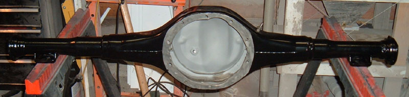
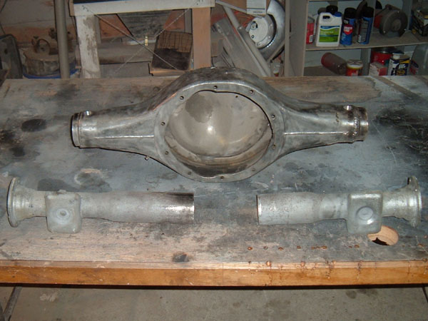
Q. What do you get if an 8" rear end housing from a 1966 Mustang and a 9" housing from a 1969 Country Squire meet in my garage??? A. 9" housing with small tubing housing ends for a 1964.5-1966 Mustang
Finding
an
original
Ford housing that will work in a first generation Mustang:
When attempting to find a 9” for a first generation Mustang there are several OEM housings used in Mustangs and other models with the correct 52.25” housing flange to housing flange width. The first is an actual Mustang 9” housing. A few Mustangs actually came with the 9” housing but these units are nearly impossible to find and when you do find one they’re expensive. Other Ford options are the 1957-1959 full-sized Ford cars, the 1975-1980 Granada/Monarch and the 1977-1980 Lincoln Versailles. With these “other model” donor cars there is one immediate difference between them and an original 1964.5-1966 Mustang 9” housing and that is the Mustang housing has tapered tubing ends. A non-tapered tubing unit can be used in a first generation Mustang but different u-bolts and mounting plates will be required. Narrowing a Ford 9” rear end for a 1964.5-1966 Mustang Farming out the narrowing process: When I first
looked into this project, I
got price quotes for farming the project out to a local machine
shop. At the time, several years ago, I was quoted between
$175
and $250 to have a larger 9” unit narrowed up. None
of the
machine shops were overly interested in combining a 9” center
section
and 8” axle tubes so, had I gone that route, I would have had
to come
up with different axles since most 9” housings use bigger
bearings on
the axles.
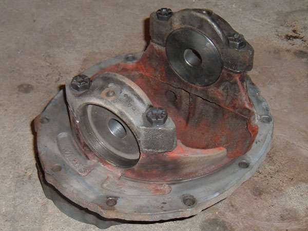
It’s all about DIY: As those of you who are familiar with my web pages know, I am all about DIY and finding ways to make it easier for other to do things themselves. Therefore, my only real option was to take an existing 8” housing and use its tubes and axles to convert a larger 9” housing into a 9” rear end for a first generation Mustang. There are several reasons I chose to do this: 1. Having the tapered axle tubing is period correct for a 65-66 Mustang, even with a 9" rear end. Of course, I only add that because it could be a valid reason, I personally couldn't care less about "period correct". I am putting a Jag IRS unit in my personal Mustang, for heavens sake. 2. By using the "period correct" tubing, existing u-bolts and mounts can be used so there is no need to source them. 3. Most Mustangs came with 8” rear ends so donor housings and axles are easy to find and relatively inexpensive. 4. The 8” axles are 28 spline, just like many of the 9” differentials, and already the correct length, not to mention that as long as you are not running slicks, a 28 spline axle can handle upwards of 400 HP. 5. All the other stock components such as brakes mount up without having to modify anything. 5. Most axle tubes from the donor 9" housing have different spring mount locations that need to be relocated or all kinds of extra mounts not needed for a leafspring suspension that would need to be cut off. 6. In many cases the O.D. of the 8" tubing is almost the same as the I.D. of the original 9" axle tubing, making the mod simple. 7. My favorite reason is because it is fun. Tools: This project starts like any other in getting tools and materials together to do the job. One can perform a mod like this with just the bare essentials such as a level, angle finder, saw, welder, and tape measure; however, having some specialized tools makes all the difference in the world. The first “specialized” tool is a measuring jig from Dutchman called a Dog-bone. This tool allows you to install the axles in the housing and check length without having to install the third member. Another tool is something I had custom made at a local machine shop and that is an alignment jig. In the case of an axle housing, it is important that the wheel bearing housings line up with the carrier bearings on the differential. If the tube is off, the axle will be inserted at a slight angle, which can cause premature bearing failure. To ensure that everything was lined up correctly, I put together a jig. I took an old 9-3/8” rear end case, removed all the differential parts, and had two pucks, with a 1” hole in the center, machined to fit inside the carrier bearing caps. I then had two more pucks machined, also with a 1” hole in the center, that have an O.D. that is the same as the two main Ford wheel bearing sizes. To line everything up, the case is bolted to the housing and a solid 1” steel shaft 6’ long is inserted through the 1” hole in the carrier pucks. Then the new axle housing tubes can be adjusted until the outer bearing pucks can be slid down the shaft and inserted into the wheel bearing housings.
One thing I decided to do to increase the strength of the “new” housing was to drill tapered holes through the top and bottom of the center section tube ends just to the inside of the original factory welds so that they could later be filled as plug welds. Since the new tubes were being welded to the original tubes and not directly to the original center section, I wanted the plug welds so that there was some direct connection between the new axle tubes and the center section. This step may not have been needed but I have always felt that the best option is to always over build.
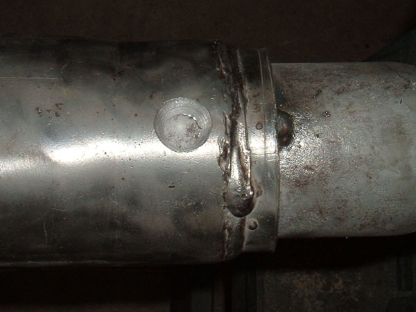
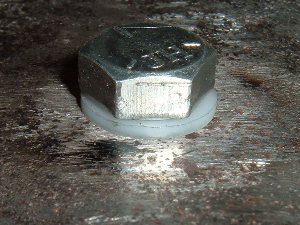
My 9”
donor housing did not have a fill
plug because, on that particular unit, fluid was put in through a fill
plug on the front of the third member. I added one by taking
careful measurements on another 9” housing I had and drilled
a 7/16”
hole on the correct location. A file was then used to make a
flat
surface perpendicular to the hole and a 7/16” bolt was
inserted through
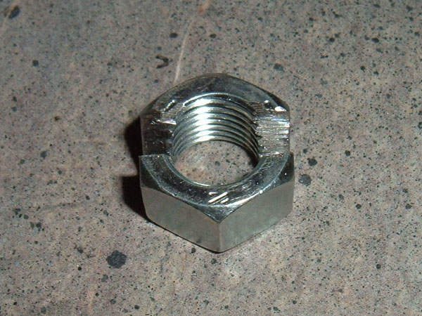
the hole. From the inside, I placed a 1/2” fine
thread grade 5
nut that I had cut down to be about 3/16” thick, over the
7/16” bolt
sticking through, and tightened a 7/16” nut down on it to
correctly
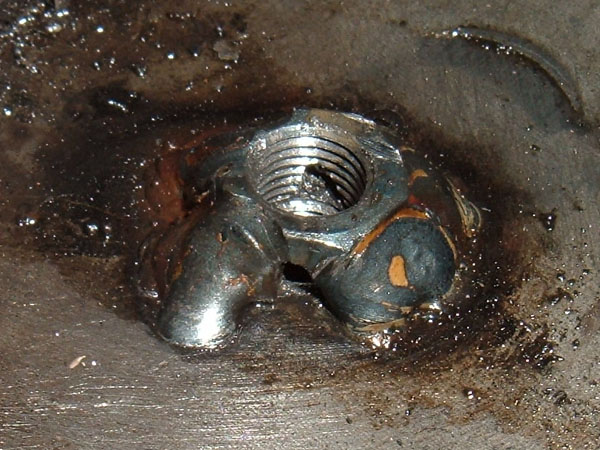
position the nut. Once in place, I spot welded the nut to the
inside of the housing and removed the 7/16” nut and
bolt. I then
double checked that the inside 1/2” nut was correctly
positioned and
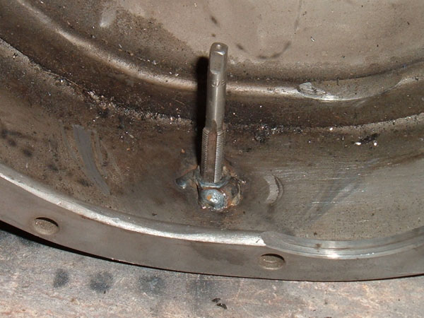
welded it on all sides. A 1/2” fine thread tap was
then inserted
from the inside through the 1/2” nut that I welded into place
and the
7/16” hole in the housing was threaded to
1/2”. This gave me
about 1/2” inch of material that a plug bolt with a nylon
washer could
be inserted into, to seal the unit. NOTE Any welding slag and
or
small welding BB’s need to be removed from the inside of the
housing. If they are not removed they could come loose during
use
and damage your differential.
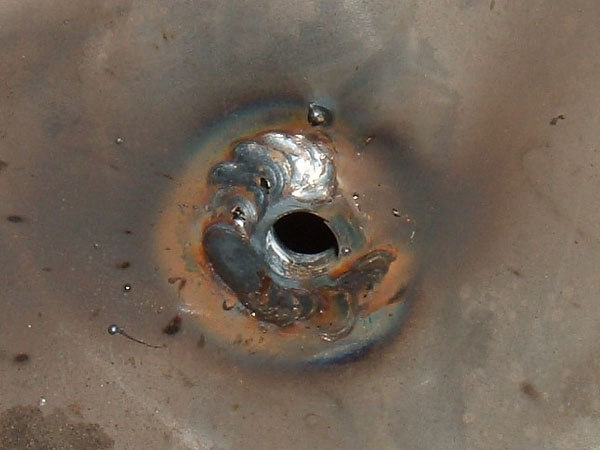
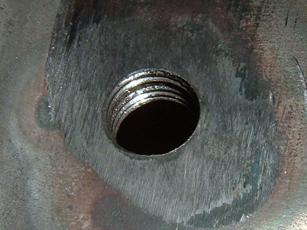
Another
modification I made to this
housing was to add a drain hole. Early Ford housings had
drain
holes in the differential housing but Ford eliminated them from later
productions to cut costs. I used the same technique as above
with
a couple of exceptions. The plug bolt was 3/8”
instead of 1/2”
and a grove was cut into the nut I welded inside so that as fluid
levels dropped below the top of the nut, fluid could still drain out of
the unit.
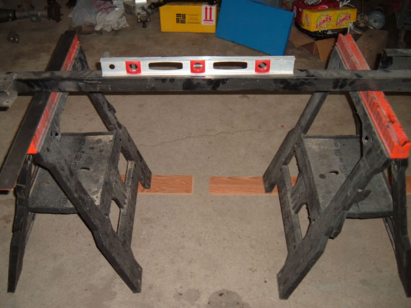
Taking
measurement:
The next step in the process was to take and notate measurement on the 8” housing prior to cutting it. Before I could actually start measuring I needed to do two things. First, I placed two saw horse 43” apart and then leveled them both directions so that all measurement would be accurate. In my particular situation my garage floor was not level at all so I had to do quite a bit of leveling. This gave me a nice uniform platform to place the housing on as I was working. Second, I took a piece of 16” X 3” X 1/8” and drilled four holes in it. The top hole to be used in all applications and the bottom three holes that corresponded with studs or mounting holes on an 8” housing face, a 9” housing face and the pinion support on the jig case. This was done so that, at any point, the steel could be mounted to a housing and provide a uniform steel surface for me to place the magnetic angle finder on to double check the pinion angle. The spring mounts of the housing were then placed on the two saw horses, the piece of steel was installed on the face of the differential opening and a magnetic angle finder was placed on the steel to find the pinion angle. I also used a tape measure and measured width from outer flange to outer flange, and width from spring perch to spring perch. For my project, I actually had two 8” Mustang housings so I took measurements from both to make sure all was the same and then used the second one as a reference when I assembled everything later. After getting a clear picture of how the final rear end needed to end up dimensionally, I cut the tubes off of the 8” housing at the welds and stripped the tubes down to bare metal.
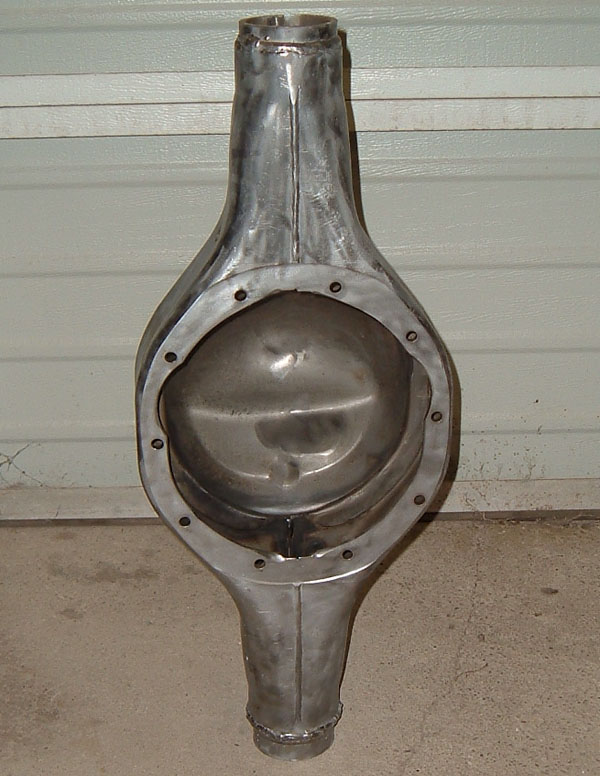
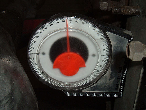
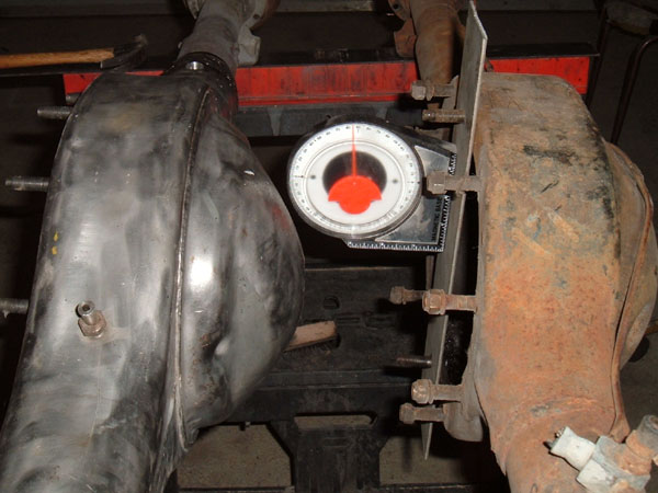
Setting
length:
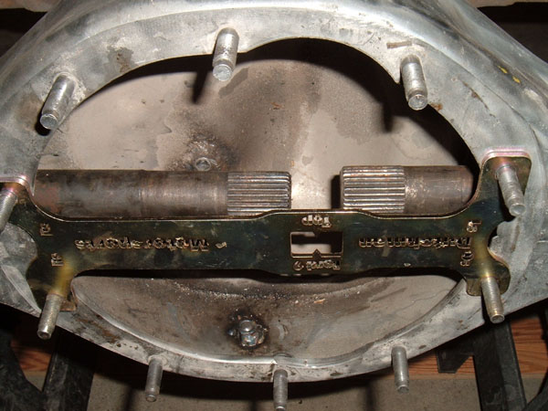
To begin mocking up the “new” housing I inserted the 8” tubing ends into the 9” housing center section and placed the unit on the saw horses. The Dog-bone was installed onto the face of the housing and a set of 8” axles were inserted into the mocked up unit. By tapping on the ends of the axles with a rubber mallet, I was able to line up the tips of the axles with the opening in the Dog -bone. Also, I took measurements to ensure the correct 52.25” width flange to flange and the proper spring perch to spring perch measurement. Once I had the depth set correctly, I wrapped the 8” tubes with electricians tape at the place where the 8” tubes met the 9” center section to mark proper tube location. Setting pinion angle: To set the pinion angle, I installed my steel plate on the extra 8” housing and once again took measurements and confirmed my original measurement that the face of the housing tilts up 5 degrees. You would think that you would want the end of the transmission to point to the differential and vice versa, however, for proper u-joint motion unseen lines extending from the pinion shaft on the differential and from the output shaft of the transmission need to be parallel. I then installed the steel plate on the front of the 9” center section and took a measurement and made adjustments to correctly set the pinion angle. I found it easiest to adjust pinion angle one tube at a time, by setting one side to be correctly indexed to the center housing section and then setting the other side to be the same as the first. By doing them one at a time, half the force was needed to rotate the axle tubes. Once I had everything where I wanted it, I reinstalled the axles and the Dog-bone, as well as took more measurements to ensure that length and axle depth had not changed while I was setting the pinion angle. After I was positive that everything was where I wanted it, I installed the jig case onto the front of the housing and the steel plate onto the front of the case. I then inserted the 1” steel rod through the housing and adjusted the axle tubes so that the outer bearing pucks could be inserted into the housing ends. With everything lined up, I measure yet again, checking length and pinion angle. With everything held in place, I removed the tape from the axle tubes that showed the correct width and spot-welded the 8” tubes to the 9” center section in three locations per tube. The housing then went to a certified welder so that a bead could be put around each tube and so the plug welds could be filled. I am a competent welder and could have run the beads and filled the plug weld holes myself, however, the $30.00 I paid to guarantee that the housing was solid was money well spent. The long and the short of it is that the steel on this housing is at the max thickness for my welder and rather than pushing things to the max, farming it out simply made more sense. The only thing left in finishing this housing was a trip to the powder coater. Axles and differential information: Any 9” third member will fit in this housing, and, other than gear ratios and differential types, they come in two varieties, 28 spline and 31 spline. The 31 spline third members utilize stronger axles and are the only choice for rear ends that will see more than 400 HP or will have hard launches, especially when running slicks and or drag racing. In order to run a 31 spline differential in this housing, the axles will need to be custom made so that they have the smaller axle bearings and are the correct length. Such axles can be purchased from places like Curry or Moser in the $400.00 price range. If the HP is less than 400 and/or you will not be running slicks and doing hard launches, such as in drag racing, then an original set of 28 spline axles will work just fine and can be taken from the same rear end that donated its housing tubes.
|