
|
|
|
|
|
All the parts
hoarding I've done over the
years is paying off!!:
|
Like most car guys I collect (hoard)
parts. The collection gets
bigger every time I part something out under the concept of "I might
have a use for that later.” There have been at least a half dozen
times
I have scrapped something that was complete junk and then though of a
use or repurpose for it or part of it. A perfect example is an
old gas tank I had from my 62 Galaxie. The tank was rusting on the
inside, dented, and not a good candidate for restoration so off to the
scrap yard it went. Then about a year later I was thinking of
making
a custom remote power steering reservoir for my Galaxie and realized
the tip of filler neck from the tank would have made a perfect top for
said reservoir but the tank was gone.
Fortunately that doesn't happen very often because I keep almost
everything and now I am glad I have because I was able to use those old
parts to build an engine run stand. When I was making plans the only
thing I figured I would need to buy was a battery.
The reason I started this project was to do a compression test on a
used 351W I picked up and plan on putting in my 62 Galaxie.
|
DazeCars
Items for Sale:
|
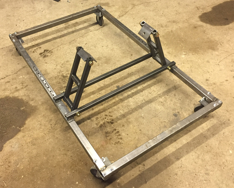
The
concept of an engine run stand is simple, a self contained place to
bolt up an engine, that also has all the parts and pieces needed to run
that engine, break it in, test new parts, and/or for
tuning. The biggest advantage of an engine run stand is it's a
lot easier to put an engine in the stand than it would be to install
the engine
in the car.
I built my stand based on the Ford small block
because that’s almost
all I ever mess with BUT I also made everything adjustable so I could
throw on other engines simply by changing out the mounts and adjusting
the bellhousing mounting plate.
IThe first
thig I did was spend some time digging through my steel pile to
find enough to build most of the stand.
I always tend to buy a little extra steel for what ever project I am
working on as I would rather have to much and be able to finish the
project rather than not enough and have the project stalled out
weighting for materials. There have been a lot of projects over
the years so there were lots of scraps to pick from. I also hate
to wast so anytime there was anything made of metal, that was no longer
being used for what it was designed for, I would remove the metal and
add it to the scrap pile. |
Lots of scrap to work with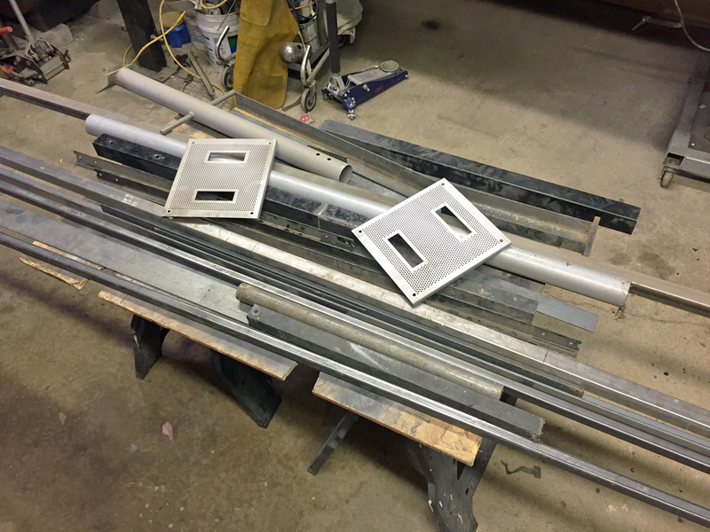
|
|
| With lots of steel to choose from, I cut the
pieces for the base. In
the
picture below, nothing
is welded up. At that point I still had to drill some mounting
holes in the pieces before they were welded together. This was a
really wise decision to drill all the holes prior to welding it
up. It
made the initial fab work take a long time but the final result was a
quality setup where all the holes lined up and were exactly where they
needed to be. |
| The above mentioned holes included ones needed
for the wheels and the
holes mid stand for adjustability. From there it was time to fire
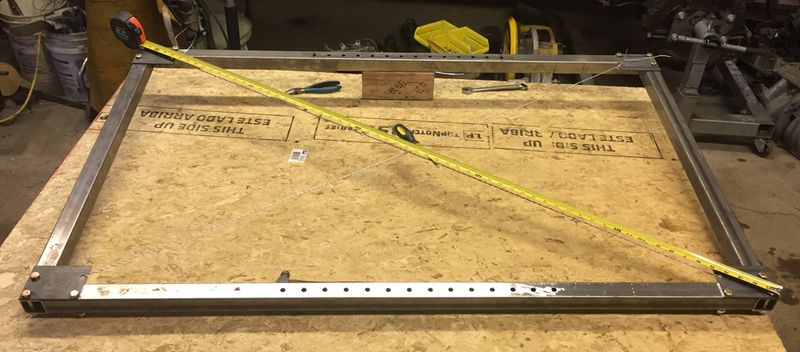
up the welder. I
bolted on the cut and drilled wheel plates to the frame pieces and then used
fencing wire crisscrosses from one corner to the other to help make it
square. |
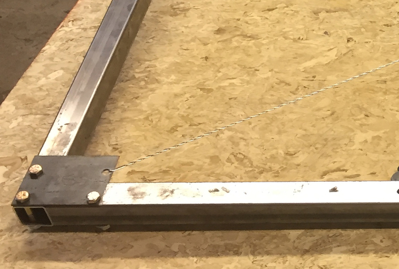
| The squaring technique I used is simple but very
effective; you twist
the wire and tighten it up on its self. Once all the slack is out
of both sections of wire you measure from corer to corner. You
then tighten the wire between the longer corners, then repeat the
measuring and tightening until both corner measurements are the same
and you have it square. As the wires get
tight they hold everything in place so there is no issue with things
moving out
of square as you are welding. |
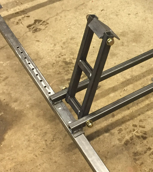
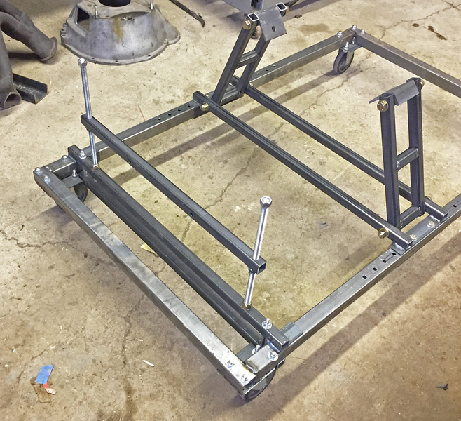
| Once I had the base built I turned my attention
to the uprights They pivot
where they attaches to the bottom mount and they pivots at the engine
mounts so everything is adjustable depending on what engine/mount combo
I might want to run. |
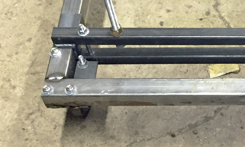
| The lock nuts are tight enough that the uprights
are freestanding but
still totally adjustable.
On the other end I made a bar that bolts to the bellhousing and than
has a piece of all-thread on either end. This will allow me to
adjust the height of the bellhousing and also level it up from side to
side. |
If I run a different engine I will probably need to make an
adapter or some minor adjustment to this end, but I won’t do that until
I need to... if I ever need to. As I said before all I ever mess
with is SBF.
The mounts for the uprights to frame are only adjustable in 1.5"
increments so I needed the bellhousing end to be completely adjustable
and I came up with a "clamping" method to attach it
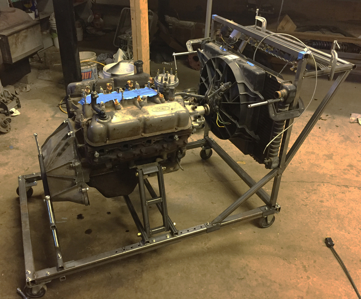
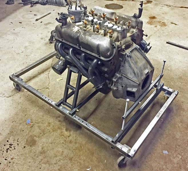
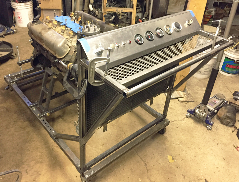
| Putting an engine on was really easy with the
mounts pivoting at two
spots. Once the engine was on I could easily move it from side to
side to level it up but not so easily that it felt unstable. Once
I hooked up the bellhousing mount it was rock solid and I could only
move the engine by adjusting my leveling screws. |
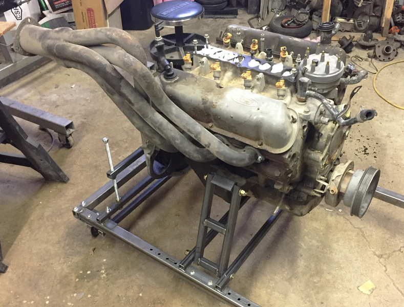
| In preparation for the exhaust I had two
options. In the above
picture I have a new never used set of shorty headers. I really
didn't want to use them being that they have never been run. I
also have a set of headers I got from a 72 F-100. I will probably
use them but unfortunately they don't clear the bellhousing mount so if
I run them I will have to reverse them and go "gangsta style" |
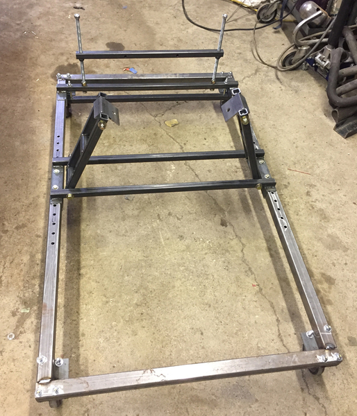
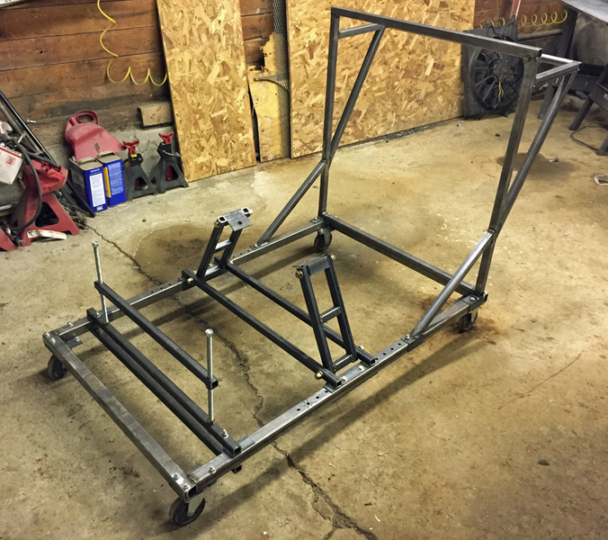
| With the
stand able to mount an engine, I got to
work on fabricating the radiator support/push handle.
This part was built from steel I had to purchase. The bellhousing
mount and the engine uprights were made from 1” square tubing with 1/8”
walls but I didn’t want this cart to be to heavy so I made the raditor
support/push handle out of 1” square tubing with 1/16” walls |
| The radiator support/push handle is bolted on
using the wheel bolts and
the end most adjustable mount holes in the center of the frame. I
wanted to make sure the radiator support/push handle could be removed
so
that the run stand takes up less space when not in use. |
| With the majority of the structure fabricated up
it was time to
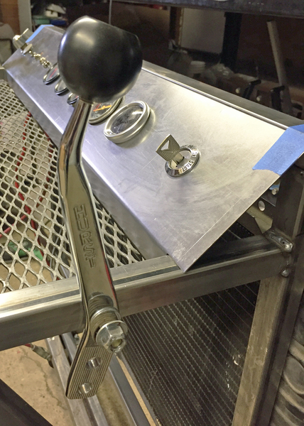
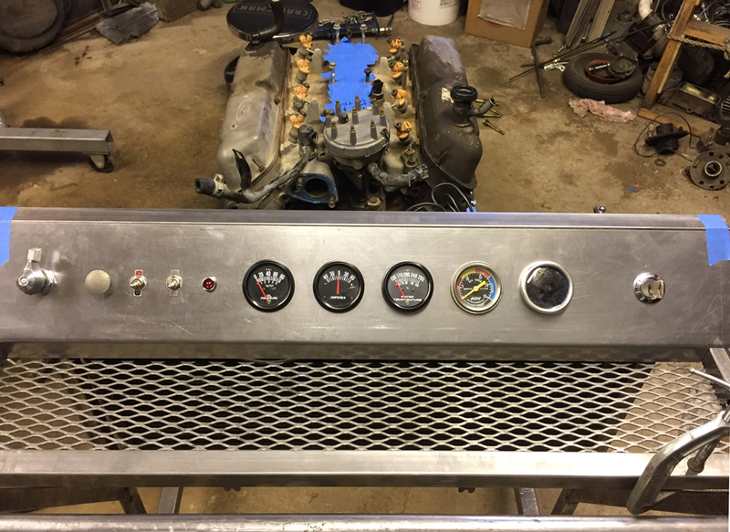
start dealing with a lot of the smaller details. The most
important detail was the gauges and engine controls.
From left to right: Battery kill switch, Manual choke cable, Electric
fan switch, High/low fan switch, Idiot light for oil if the engine I am
running is set up that way, Oil pressure gauge, Amp gauge, Temp gauge,
Vacuum gauge, O2 gauge, and Ignition switch. |
| The expanded metal at the base of the gauge
cluster is a tray for tools
and parts when tuning an engine. |
| I then added a radiator from an 84 Mercury
Grand Marquis and an electric fan from a Mark VII. This fan and
has
two speeds. I will be wiring it
with three options: off, low and high.
In the spirit of reusing parts I used a Hurst shifter as my
throttle. |
At this point It’s
basically done. I will leave it alone until
the 351 is ready to be fired up and then finish wiring in the
electrical and such for the test fire and after said test fire I will
take the stand apart one last time and have it powder coated. I
figure there will be some minor adjustments that will need to be made
to run it so I won't cote it until I have had the opportunity to make
those adjustments.
|
© 2013
DazeCars
The words / logos for Ford, Jaguar, Mustang, Galaxie, etc are used for
descriptive and reference purposes only. DazeCars is neither affiliated
with Jaguar Land Rover North America LLC, Ford Motor Company nor the
manufacturers/distributors of Ford or Jaguar automobiles. |
|
|