 |


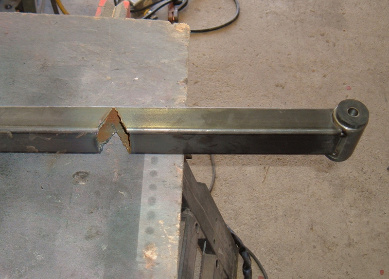
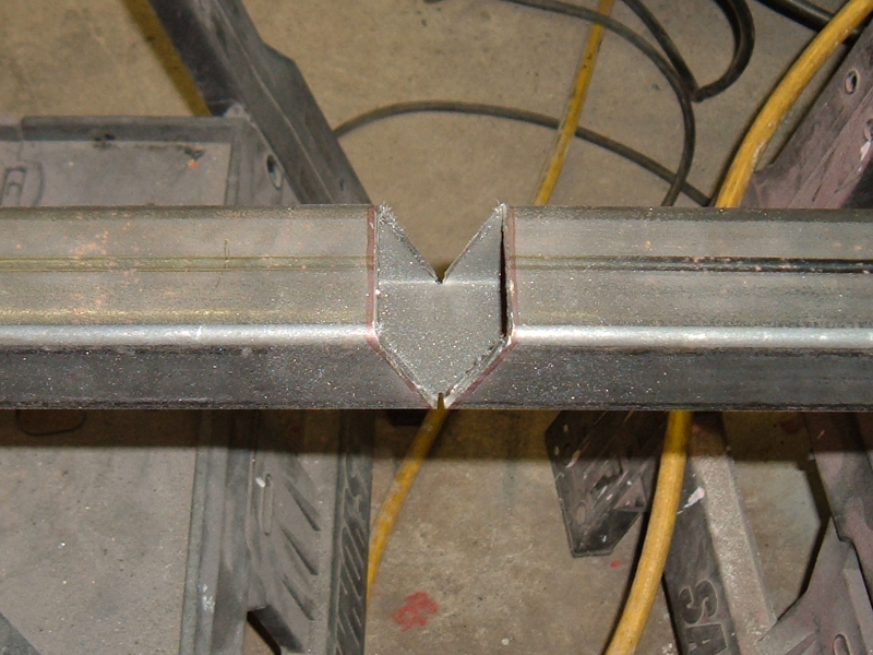
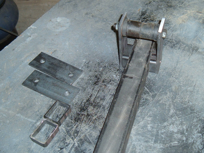
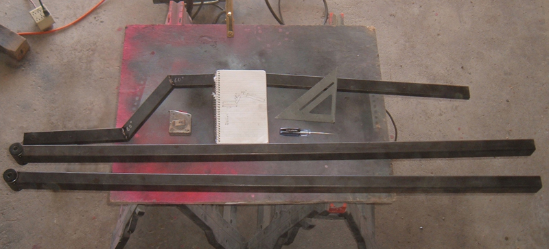 Steel, a pattern, and fabrication tools. Everything needed to build side rails The notch bend a weld technique: Some years back I built my own weld in sub-frame connectors. I wanted something that contoured the underside of my Mustang and connected the front frame rails to the rear frame rails. This required a square tube that had bends going on two different axis. A tube bender would have worked well to make this part but I do not have one and as you know I am all about keeping it DIY so I came up with a technique I call "notch bend and weld." It allowed me to easily make the bends in the tubing without compromising strength. I mention all this because I used the same technique to make the side rails for my IRS install. The concept is really simple. You start by cutting a wedge shape out of the square tubing. The angle of each half of the wedge needs to be 1/2 the total angle needed at the bend. A real world example of this would be a picture frame. At the corner you want 90º. To archive this, each piece of the the frame material is cut at a 45º angle with the two cuts being opposite of each other. Exact same concept applies to notching the tubing to build the side rails. On my side rails he two sharpest angles are 55º so in theory each side of the wedge would need to be 27.5º. The reality is I wanted a little bit of a gap to fill with weld and I also wanted some adjustment prior to welding so that I could get everything exactly where it needed to be. With this in mind I made my cuts at 30º per side to make the 55º bend. When cutting out the wedge there are a couple things you need to do to insure a good bend. First you need to use a square and mark a line, through the middle of the desired bend, all the way around the tube. This line gives you a reference to insure the wedge is uniform in shape.
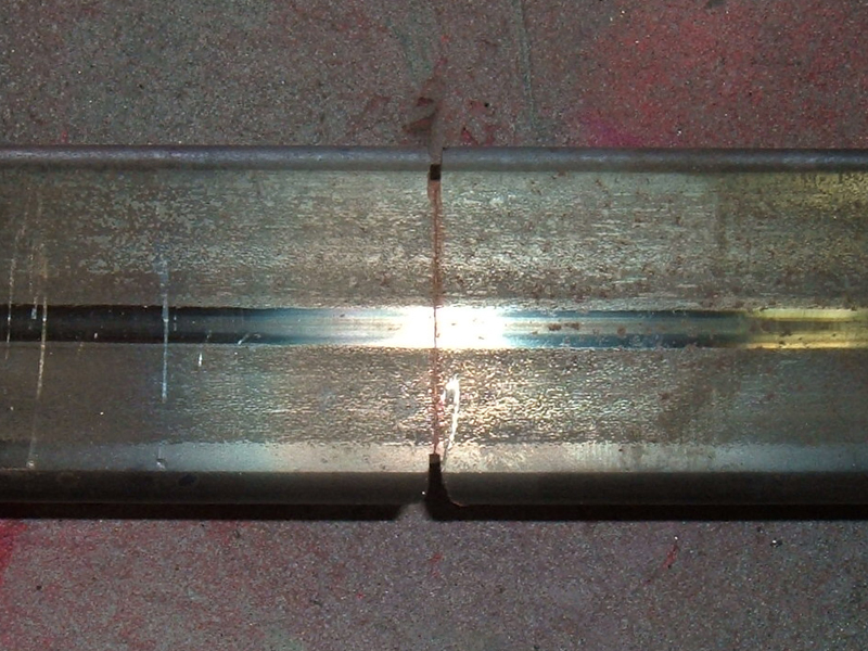
The second thing you need to do is cut into the outside edges of the bottom side of the tubing. (the side that will be bent when you close the gap) The way square tubing is made there is a radius on each corner. If you do not cut through that radius it will be harder to bend and when you do get it bent the corners will pucker out and not be uniform. If you look at both pictures below you can see the cuts I am talking about.
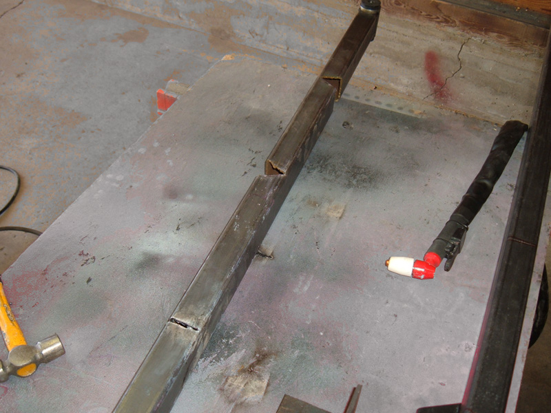
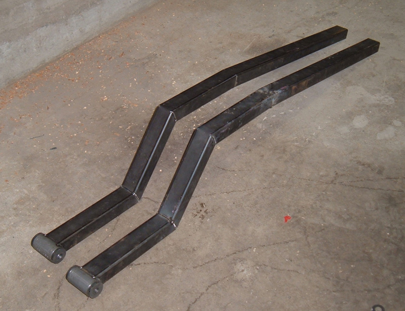
When I first started building these side rails I used a plasma cutter to cut out the wedge and then a cutoff wheel to cut through the corners on the bottom side, but after a few notches I realized the cutoff wheel gave me a cleaner cut with better control so I used it by it self to do all the remaining cuts. Once I had my notches cut and cleaned up I bent the side rails so that the first joint was at the angle I needed and tacked welded it together, I then moved on to the second and third joint repeating the process. I used my pattern as well as angle finding tools to build the first side rail. After I had it together I test fit it in the car and made sure it fit as well as the pattern had, which it did. To make the second frame rail I repeated all the steps from the first rail but instead of using my pattern and angle finding tools to get the correct angles at the bends, I used the first frame rail to line up the second frame rail so they were an identically matched pair.
I have documented this project both on this web page as well as on www.IRSuspension.com forum and there are at least three Mustangs out there with a Jaguar IRS under the rear, and while many things on the IRS install on these other cars were done differently than the way I did mine, every install uses my side rail concept. If you have not figured it out yet the primary function of DazeCars is to share information and help others build or modify their classic car, especially if they want to make your classic ride "better". So when I was contacted through the forum, by the fabricator who would eventually install three IRS units in Mustangs, asking for specific information to begin his own IRS install, I was more than happy to help. "Daze,
I am ready to build the
side supports and just thought of asking for the plans. My car
is on the ground and drivable so preparing everything and then making
it a one day job is what I prefer... Can you give me the
measurements for the side supports?"
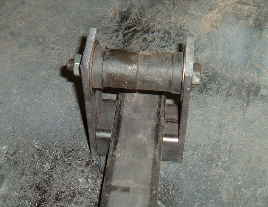
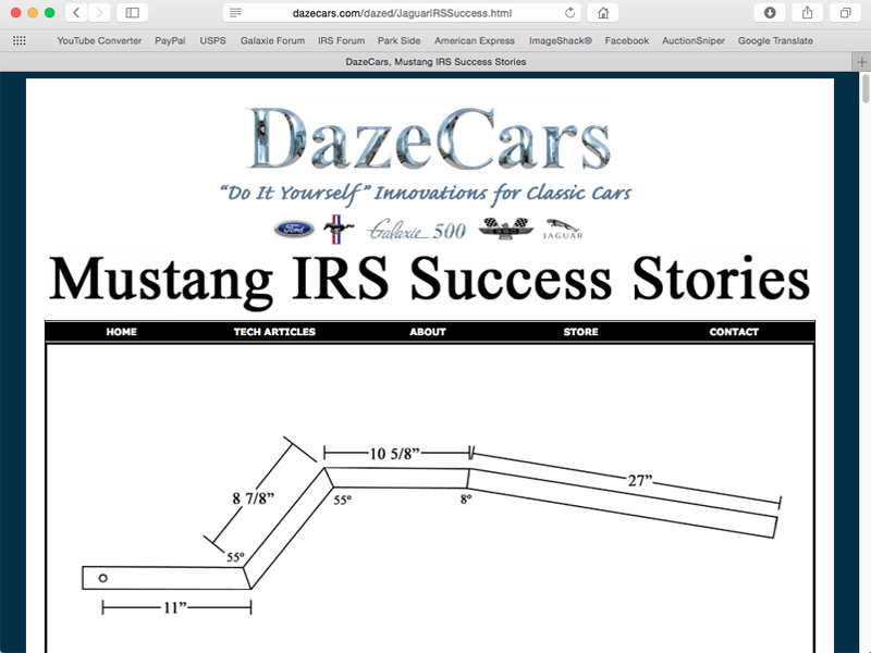
Mustsed "This drawing is not to scale, but should give you a general idea of what I have going on. Let me know if I can help further." Daze 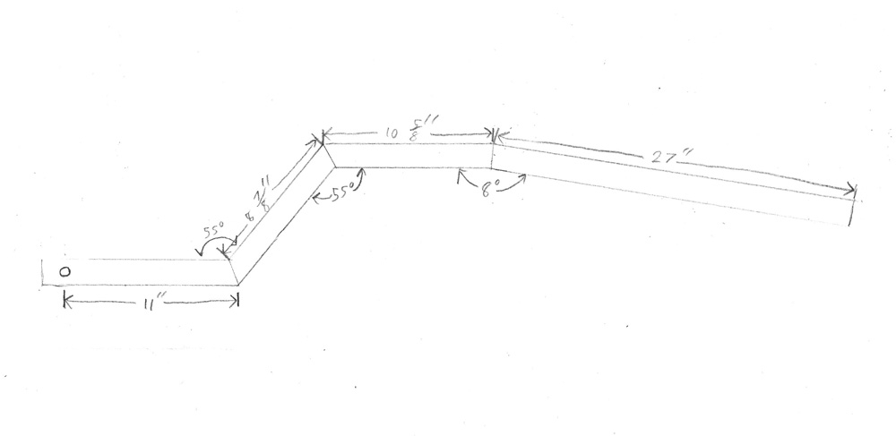 This is a scan of my original hand drawing. There is a cleaner drawing at the top of my Mustang IRS Success Stories page Rear Shackle Mount: When it came to the rear shackle mounts I had several ideas, some of which were better than others. Just like the custom mounts I made for the front, my rear rubber mounts are typical 9/16" hole Mustang shackle bushings. To add rigidity and get the ID to 1/2" I press a 5/8 sleeve in to the bushings. The internal steel sleeve goes in fairly well but does take a little pressure and had me wondering what the best idea for the rear mount was. I could use the stock upper hole in the frame, install the shackle bushings as designed and then run a solid steel piece that is welded to the side rails and connects to the OEM mount. This idea is the most straight forward, but I am worried that I will not be able to get the 3" sleeve pressed in to the two bushings to tie them together, do to the limited room to work where the bushings are located in the car. The second idea was to set it up the same as above but use poly bushings which are way more rigid and already have the 1/2" ID hole. The problem with this is I don't like poly, it doesn't flex enough IMHO and I am worried that there will be more flex in the front than the rear because the front bushings are rubber. Third option is to use a shackle design utilizing the poly bushings in the Mustang frame and then weld a sleeve to the end of side bracket like the one in the front to house the rubber bushings in the lower shackle location. If I did this I should have fairly even flex, front to rear, but now I am using two sets of bushings and even more fabrication will be required. I posted these ides on the forum and got lots of replies. The IRS forum is a fantastic place for brain storming and I used the collection of minds there often when problems came up so that I could achieve the best possible solution. Ultimately I came up with a design that has both the ease of install and the similar mounting flexibility to the front bushing. I realized I was making it way to complicated. The fix was to use one set of rubber bushings in the Mustang frame as originally designed, and hard mount the lower part of the "shackle" to my side rails. Inside the Mustang frame rail I use two rubber bushing with a 1.5" sleeve instead in each one instead of of one 3" sleeve runing through both bushings, that way I can press each steel bushings into a rubber bushings, and then install the bushing/sleeve combo independent of each other. The second issue with the shackels was I had originally intended to use two pieces of 1/4" flat stock like shackles and weld both of them solidly to the side rail then run a bolt through the bushing/sleeve combo at the frame. Problem was the space between the upper frame mount and the gas tank or the frame and the rear quarter panel is not large enough to fit a bolt long enough to go through the bushings and "shackle" pieces. Normally when installing new shackles you put the bolt through the flat bar and then slide one bushing over the bolt, from there the inner bushing is inserted in the frame and the opening for the bushing in the frame is big enough that you can angle the bolt, flat-bar, bushing assembly into place. I would not be able to do this if flat bar pieces are welded to my side rails. The solution to this issue was to drill a hole through the flat bar and my side rails, and bolt both the frame mount and the side bar mounts in place instead of welding them to the side rail. Basically I am using the OEM shackle concept to mount the rear of my IRS sub-frame.
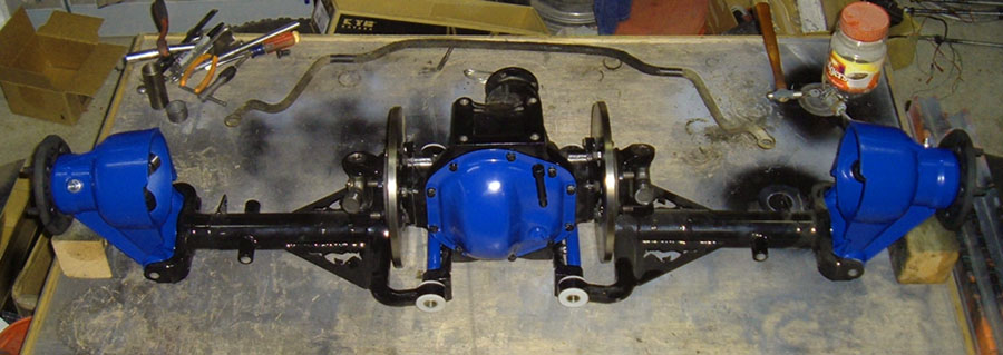
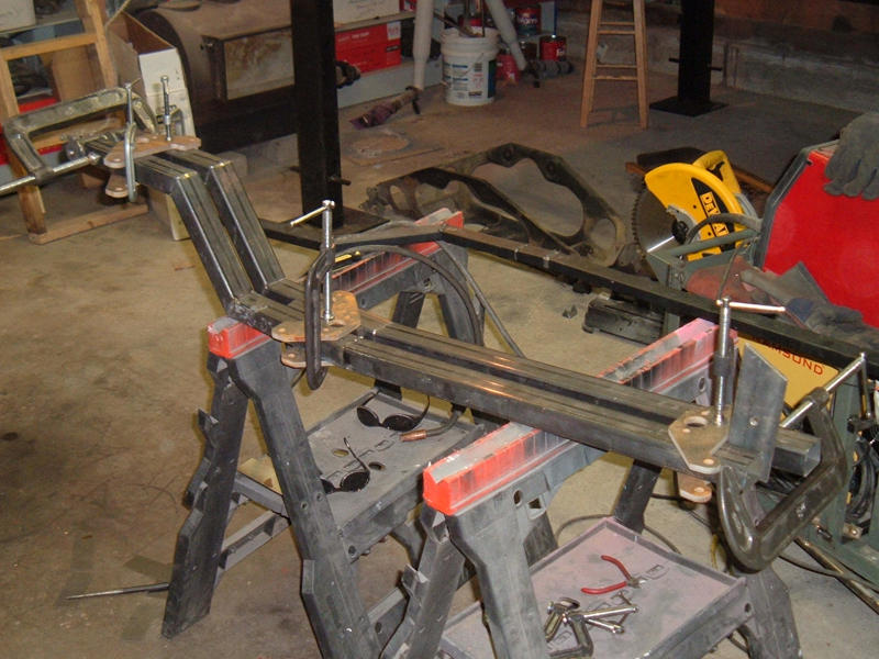
Above we have the final rear mount design. The spacers will be welded to the side support and then the inner shackle plate will be welded to the spacer. A 1/2" bolt will then go through the welded plate, through the spacer, through the side bracket through another spacer and then pass through the removable shackle plate. I would love to know the actual tolerances Ford used when they built the Mustang 45 years ago: At this point my side rails were welded up solid and mounted in the car. The two side rails were identical to within a 1/32", but when I bolted them up in the car I discovered that the original frame rail mounts were not identical. On the drivers side (side I took the measurements from) the shackle plates are at a perfect 90º in relation to the back half of the side rail, but on the passengers side the same shackle brackets are a couple of degrees off of 90º. I don't really think this is an issue other than the fact that it really bothers me. Also the passengers side, side rail sits about 3/32" closer to the Mustang frame rail at the top of the frame rail arch. The good news is that the side rails are still level at the top section front to back on both sides, and the side rails are still level in relation to each other, and since the car is currently level, I know that I can proceed in spite of the differences, but the side of me that strives for perfection sure wishes the car was a little more accurate. For your viewing pleasure, my mocked up support system: I got the support system roughed in. The crossbars are not yet welded in (or correctly positioned in the picture). When this picture was taken, the hardest part was calculating the differential location. I was mounting the top of the differential flush against the crossbars so the pinion tilts 5º up to match the transmission's down angle. Angling the pinion up shafts and wishbones forward so I had to calculate how much so that the differential can be moved back far enough to center the tire in the wheel well at ride height. Also I had to figured out the off set between the cross bars and differential so that the upper shock mounts would bolt to the cross bars. I measured many times before I was able to mock things up. 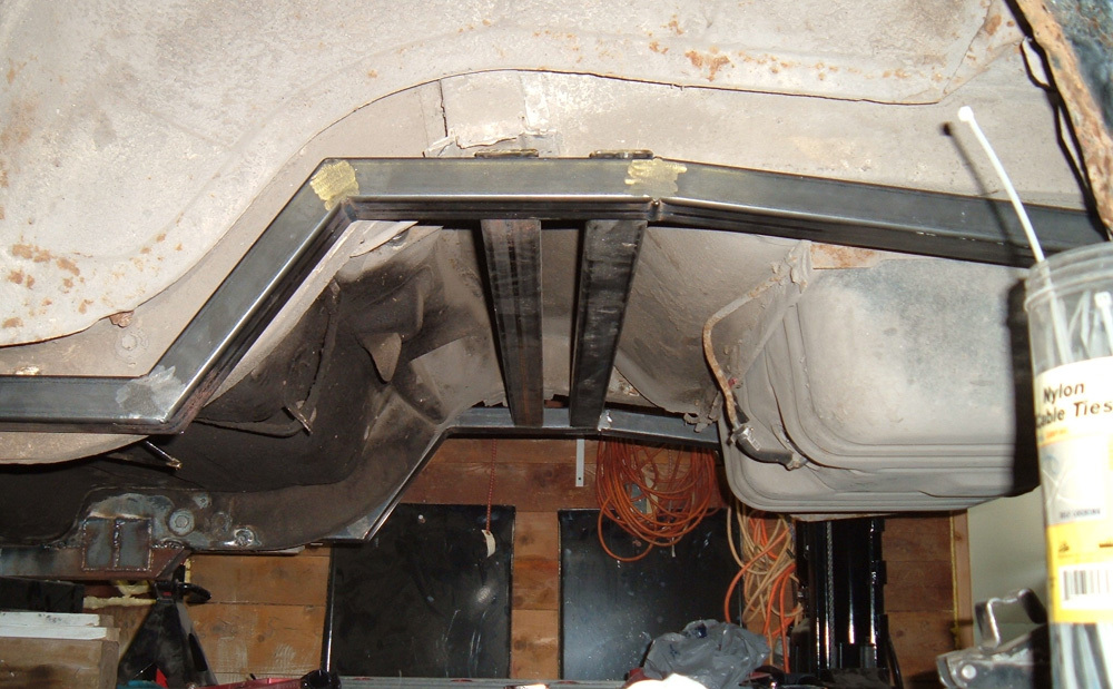 With the side rails installed and the crossbars coming together I was a lot closer to mocking up the rear end. In page VII I will address the brakes including their rebuild and address the fabrication required on the crossbar to make them fit.
|