Mustang
IRS Page II:
The
fallowing
information is the second web article on installing a Jaguar IRS unit
in to a 64.5-66 Mustang. This article covers: where to get a unit, what
to look for, tare down in to key components, and cleaning. If you have
not seen it yet I recommend looking at Page I
of this series, which describes the reasons for making the upgrade and
compares the Jaguar IRS unit to the original IRS unit ford designed for
the early Mustang.
Finding
and Building a Jaguar IRS Assembly:
In order to
retrofit a Jaguar
independent rear suspension into a classic Mustang, or any other car
for that matter, first you must find a Jaguar rear end assembly. Since
the best units for this purpose are from 1960-1987 various model
jaguars, the unit WILL be used, more than 20 years old, and thus will
need to be completely dissembled, cleaned and inspected so that parts
such as bearings, seals, pads, rotors, or maybe even ring and pinion
and carrier can be replaced.
Finding
an IRS Unit: If you live in an
area with minimal
population such as my home state of Montana, the simple act of finding
a unit at a reasonable price can be challenging. I called
every
junkyard in the seven major cities in the state and only found one
Jaguar and it was too new. I found several options two states
over in Seattle, Washington, but it was still going to cost me $600.00
for the rear end assembly and then another $200 to have it shipped to
me. Prior to starting this project, I was under the
impression
that Jaguar rear end assemblies could be had for less than $300.00 so
this information was most disheartening. Not being one who
takes
no for an answer, I began looking on-line for a Jaguar forum because I
knew most automotive forums have a classifieds section. Such
a
forum, and corresponding classifieds section, put me in contact
with David
Boger
of Everyday
XJ,
who parts out Jaguars. From there, getting
a
rear
end assembly became MUCH easier. David had a wide range of
choices including gear ratios from 3.54:1 all the way to 2.88:1, coming
out of many different years of cars. David sold me two units,
the
first cost $200, and that included him strapping it to a pallet and
dropping it off at a local freight company (freight collect).
The
second unit also cost me $200.00 but David broke it down for me, (for
an
additional fee) so that it could be shipped FedEx ground in 3 large
boxes. Shipping it FedEx rather than truck freight reduced
freight charges by over half, but eliminated the ability for me to get
the cage on the second unit, fortunately I did not need it. The unit
for the Mustang project has a gear ratio of 3.54:1 and came out of a
1972 XJ6. Besides the gear ratio being ideal for my
application,
this unit was an excellent choice because it came from a car that had
been a driver so the bearings and other greasable parts had been
maintained. In retrospect, getting a rear end with well
maintained greaseable parts is IMHO far more important than the correct
gear ratio because the gears can be changed out for any of the many
gear set ratios available for the Dana 44 in the aftermarket, even
though, as mentioned in the first article, the differential in a Jaguar
IRS unit is not exactly a Dana 44. NOTE when purchasing an
assembly or removing one from a donor car, make sure to get the yoke
from the end of the driveline that bolts to the differential.
A
standard Ford u-joint fits in that yoke and will allow you to easily
mate the Jaguar differential to the driveline in your car.
Choosing
a Donor Car:
As mentioned in
page 1 of the “Mustang
IRS project”, the Jaguar rear end has remained mostly
unchanged in all
the various models of Jaguar from 1960-1987 with the exception of
wheelbase width from hub to hub. Because of this, most of the
moving parts from the various years are interchangeable. When
attempting to locate a unit, the easiest way to know what you are
getting is to look at the model and year the assembly came out
of. The following is a basic list of what a given year and
model
of Jaguar will have for a rear end assembly, however, this list is just
a guideline and probably not all-inclusive.
Year
Model
Series
Track
Width
Gear
Ratios
Powerlock
Oddity
1960-1963
XKE
I
53.125”
3.54:1
all
hub
1964-1967
XKE
II
53.125”
3.54:1
or
3.31:1
some
hub
1968-1970
XKE
III
53.125”
3.31:1
some
hub
1970-1974
XKE
56"
3.31:1
some
hub
1960-1969
3.8S
56"
4.54:1
or
3.31:1
some
1969-1973
XJ6
& XJ12
I
61.75”
3.54:1
XJ12
Ball
bearing
stub axles
1974-1979
XJ6
& XJ12
II
61.75”
3.31:1 or
3.07:1
XJ12
1980-1981
XJ6
& XJ12
III
61.75”
3.07:1
or 2.88:1
XJ12
1982-1987
XJ6
& XJ12
III
61.75”
2.88:1
XJ12
It is important
to note that all the units from the 1969-1987 XJ6-XJ12
are basically the same except the differential axle bearings on the
pre-1975 units use ball bearings rather than roller bearing.
These bearings are no longer made and the only way to replace them with
the more modern roller bearings is to replace the differential axles
with axles from a 1975 or newer assembly. Fortunately, there
is
not much strain on these bearings and they can be completely dissembled
and inspected. Assuming no problems are found, they can be
reassembled and used for many more years/miles.
Even though IRS
rear end assemblies are
available in many Jaguar models, the best choices are the 1969-1987
XJ6-XJ12. The simplest reasons are cost and availability.
Depending on the year and model, an XKE is a $20,000- $100,000
car. With these kind of car prices, it stands to reason that
the
rear end assembly out of an XKE is probably more valuable to the Jaguar
community and, hence, will cost much more than the nearly identical
unit out of an XJ6-XJ12, so why mess with an XKE. Not to mention, in
populated areas, due to availability, purchasing an entire XJ6-XJ12
parts car may be cheaper than just the IRS assembly from a
junkyard. It is important to note that all the
parts in the
XJ6-XJ12 units all years up to 1987 are interchangeable, but some of
the parts on the early XKE units are not interchangeable with the other
models and years.
Disassembly Advice:
Once you have your
Jaguar IRS unit, next
comes the task of disassembly and cleaning. When it comes to
a
task like this, I have five important pieces of advice that aply to all
rebuilding projects:
Get
a GOOD Shop Manual:
I have a
collection of shop manuals and
have at least one for every type of vehicle I own. If some part on one
of my cars came from a different vehicle, I locate and purchase a shop
manual for the make and model of the donor vehicle as well. I
was
able to purchase a CD on eBay for under $30.00 that was the full shop
manuals for the various Jaguar makes and models in PDF
format.
Any time I need to work on a specific section of the IRS assembly I can
simply print out the pages I need. Having such a reference tool is
important due to torque specification, tolerances, exploded views of
assemblies and all the directions it gives in basic rebuilds and
repairs.
Throwaway NOTHING:
As you begin to
pull things apart you
will find parts such as seals or small pieces that are so obviously
worn out that you may have the urge to throw them away, DON’T
DO
IT! The problem with prematurely discarding things is once
you
throw something away you no longer have it for a reference. When
working on any rebuilding project, I always take things apart and after
everything is back together, I then consider throwing out things that
are no longer usable. Having the original worn parts can
often
times make finding the replacement parts much easier, or in the case of
not being able to find a part, having the original part is essential
for fabricating a replacement.
Mark EVERYTHING:
As stated before
you are rebuilding a
used unit. As parts are used, they often times get certain
wear
patterns. That means that if a part comes from a specific
place
or side of the rear end assembly and is being reused, then it needs to
go back where it came from. Also, knowing the approximate
starting location of a part can be a huge help during reassembly. Often
times, these types of projects can last weeks or months, which makes
remembering part location more challenging. The easiest way
to
accommodate marking locations is to mark things as either
driver’s side
or passenger’s side. A Sharpie marker and a good
punch set can
easily aid in this process.
Take LOTS of
Pictures:
In
today’s age of digital cameras, there
is no reason (short of not having a digital camera) not to take many
pictures during the disassembly process. These pictures can
be
used later to ensure that things get reassembled correctly, not to
mention they are wonderful to have if you want to create a web page
documenting your work. :) I like to take pictures of the
complete
assembly, as things come of, and an exploded view once all the parts
are off, especially if there are several smaller parts that go together.
Find
a GOOD forum:
The Internet IS an
increasable tool for the restoration of cars and trucks all makes and
models. Not only is it filled with tech articles just like this one,
but it is also a wonderful place, through the many forums and message
boards, to meet and exchange info, ideas and experiences with others
from all over the world that have done or are in the process of doing
similar things. One such Mustang forum “FYI Ford”
put me in contact with an individual who had already put a Jaguar unit
in his Mustang, another that had done the install in a street rod and
their ideas and experiences have been a huge help. Also there is a
wonderful Jaguar forum “Jag-Lovers”
that is a good place to go if you have questions specific to the Jaguar
parts you are working with. Keep in mind that some Jaguar owners are
not happy that the IRS assemblies, from their favorite cars, are being
used on other makes and models, so it is often times best to tread
lightly and not take offense with the occasional poor comment.
If
you take the time to understand and except the forum personality than
all will be fine. As a whole they have welcomed me with open
arms. Sometime after these pages launched I found there were lots
of people out there interested in IRS so I created an IRS specific
forum IRSuspension.com
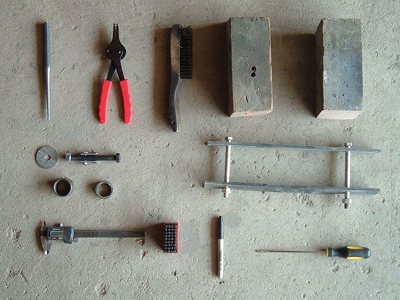
Tools
Needed:
- SAE wrenches and
sockets
-
Long Punch or 5/8” rod
-
Snap ring pliers
-
Wire brush
-
Cleaning solvent
-
Small compartment bins or cans
-
Press
-
Hub support (home made)
-
Needle bearing puller (home made)
-
Digital calipers
-
Notepad
-
Sharpie
-
Punch set or center punch
-
Screwdriver
Disassembly:
Breaking down
the
Jaguar IRS unit into
its main pieces: cage, differential, disc brakes, half shafts, Lower
Control Arms (LCAs), shocks and hubs, is relatively simple. Start by
first making sure all fluids have been drained from the differential,
and once this has been done, the unit can be flipped over so that it is
sitting on the floor upside down.
Now you
can remove the bolts that
attach the bottom plate to the cage and differential. Once
the
plate is off, start at one end and remove nuts, washers and shafts
attaching the LCA to the hub, taking care to separate out all the small
pieces into bins (this applies to all small pieces further in the
process, keeping parts separate and their location notated).
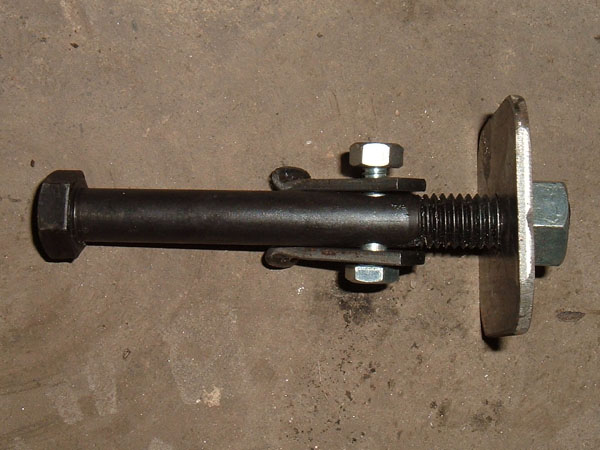
The
shaft connecting the LCA to the hub will need to be driven out with a
punch or rod. Repeat the process on the other side.NOTE once
the shaft
has been removed, the hub and half shaft will drop so make sure the hub
is supported so that you can set it down rather than letting it fall
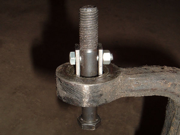
and risk damaging it. Next remove
the nuts, washers, shaft
and
spacers attaching the shocks to the LCAs. Once again the shaft will
need to be driven out. The only thing left holding the LCA is the nuts,
washers and shaft that connect it to the cage and differential, and
once said shaft and nuts have been removed, the LCAs can be lifted
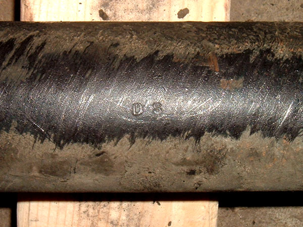
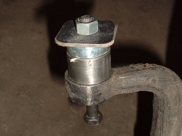
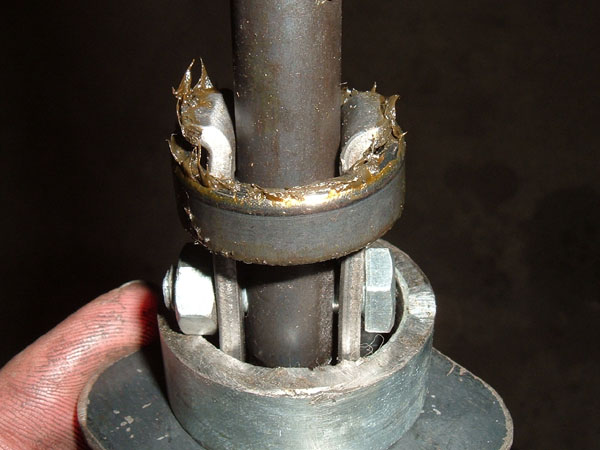
out. NOTE between
the LCA and the cage is a series of
washers,
spacers and seals, this is one of those times to either notate or
photograph their location, also once the LCAs have been removed be sure
to stamp them as DS or PS for drivers side or passengers
side.
Such marks will be needed on all further parts that are
removed.
DO NOT stamp any of the aluminum or machined surfaces because you can
damage them. To mark such parts simply clean off a small
section
and use a Sharpie.
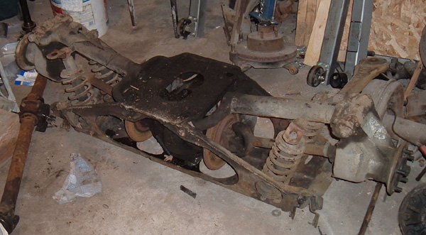
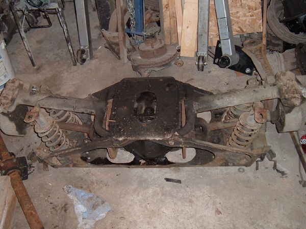
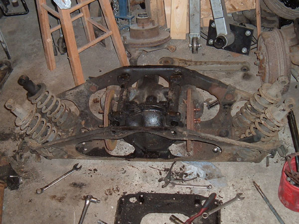
IRS
unit ready to be disassembled
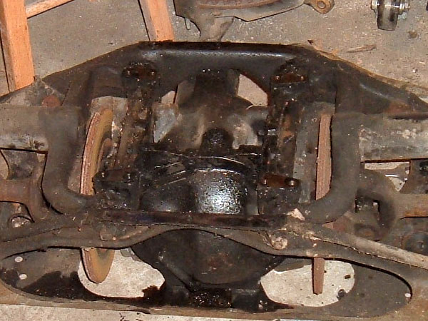
Cage
Plate removed to access LCAs
LCA
stamped DS (Drivers Side)
Now that the
LCAs
are out, there is easy
access to the four nuts holding the inner half shaft
u-joint yokes to
the disc brakes and differential axles. Once these nuts have
been
removed, the half shafts can
be pulled
free of the assembly with the
hub and set aside for further disassembly later. NOTE between
the yoke
and the disc brake rotor on each side is a series of shims that are
used to adjust camber. Make sure to remove them from the back
of
the yoke or from the front of the rotor and save them since they will
be needed later.
The only thing
left in the cage should be
the
differential with brake assembly and the four coil over
shocks.
In order to remove the differential, you must first disconnect any
e-brake bracketry and springs as well as brake hydraulic lines between
the cage and differential. Once these parts are disconnected,
the
differential and cage can be rolled over into the upright position with
the cage on top. Remove the four bolts that connect the
differential to the cage and the cage can be lifted off leaving the
differential and brakes as a stand-alone assembly. Four bolts
hold the coil over shocks to the cage and removing them completely
empties the cage.
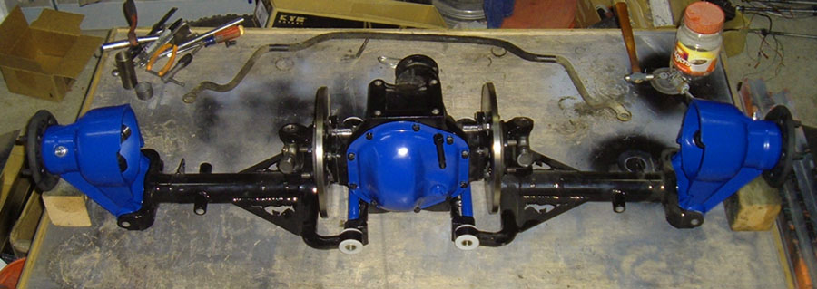
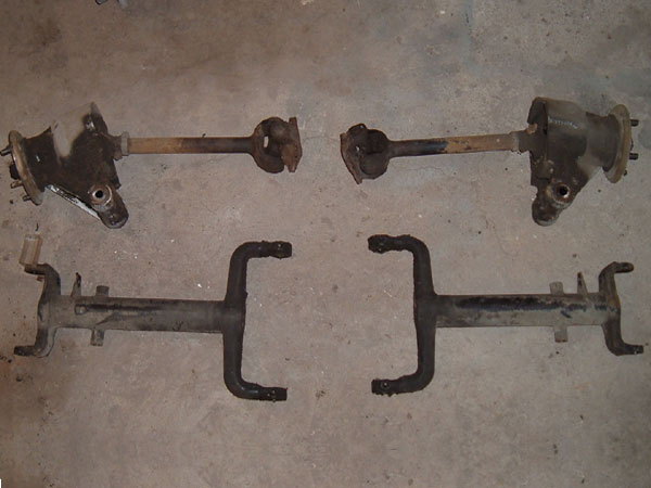
Half
shafts/hub assemblies and LCAs
Unit
with out LCAs and half shfts
Empty
Cage
At this
point, I
set the differential
assembly up on a workbench so that I could finish stripping
it.
Each caliper is held on with two bolts and, once the calipers are
removed, the rotors will slide off of the differential axles.
You
can then
either remove the five bolts on each side that hold the
differential axles to the differential, or you can leave it as an
assembly to be dealt with later in the differential rebuild/freshen
up. The only thing left to break down is the half shafts and
hubs. To remove the half shafts from the hub, remove the
keeper
pin, castle nut and washer from the end of the stub axle. Now
the
splined shaft can be pressed out of the hub and ,once they are free,
the unit has been broken down to all its key components. NOTE there
is
a specific thickness spacer between the wheel flange and the splined
end of the half shaft. That spacer is there to set hub
bearing
preload and may be different from the one in the other hub so I
recommend measuring the thickness with a set of calipers and notating
it to ensure the spacer is returned to its original location.
After talking to a Jaguar rear end expert, I learned that most of the
time, even if you replace the bearings and races, the spacer(s) that
come out of any given hub will usually be perfect to correctly set
preload during reassembly.Each component is
now ready for further
breakdown.
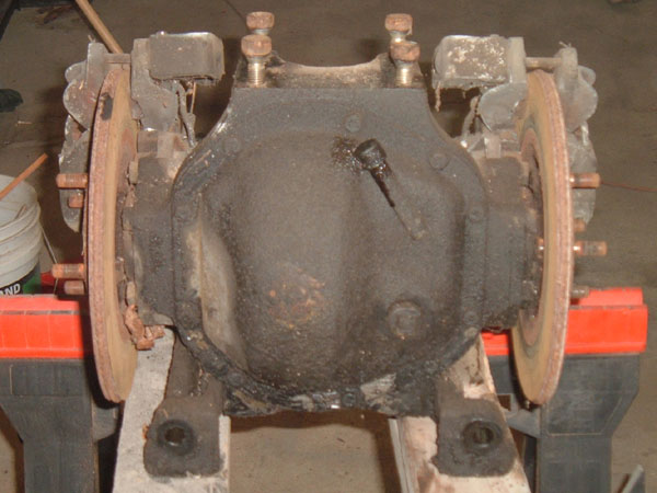
Differential on
a workbench so that I can clean and further disassemble
it.
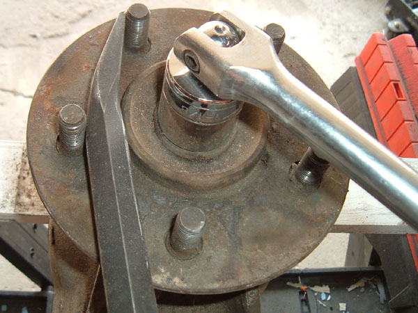
use a pry bar to hold the flang so the castle nut can be loosened
machined seal plate and preload spacer from between hub &
splined yoke
There is
still
further breakdown that
can be done to the LCAs, hubs, and half shafts. There are two
sets of needle bearings and one zirk on each arm of the LCAs on the
differential end. The zirks can be removed by unscrewing them
but
the needle bearings will need to be pulled using a puller to avoid
damaging them. For this task, I built a puller by making two
claws out of .125” thick .5” wide strap steel and
by drilling a .25”
hole in them and a .5” bolt so that a .25” bolt can
be used to hold
them together. A section of pipe, a washer and a nut
completed
the tool. To use it, I placed the bolt inside the bearing
opening, positioned the claws, bolted them into place, slid the spacer
and washer over the bolt and installed the nut. Tightening
down
the nut pulls up on the bolt and claws and pulls the
bearings.
This puller is the first of five tools and/or jigs that I have had to
make to work on this project. Now that the LCAs have been
completely disassembled, work can now begin on the hub
assemblies.
Home
made bearing puller
Pullerinstalled
in the LCA bearing
Spacers,
washer, and tightening nut
Bearing
removed
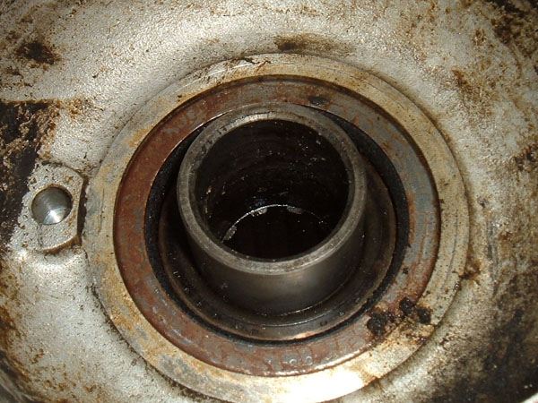
The hub
has many
bearings and seals at
both the LCA mounting point and at the wheel flange. Before
removing any of the bearings and seals, I recommend removing the zirk
on the bottom of the hub between the two LCA mounting points.
Failure to do so may result in accidentally snapping the zirk off while
working on the other parts of the hub. To remove the LCA bearing
components from the hub, start by popping out the washer and
spacer. Under that you will find a cloth seal that needs to
be
pulled out and then the bearing retainer under it needs to pried
out or taped out from the other side. Once the retainer has been
removed, the bearing and bearing shim will come
loose, and below the bearing is the bearing race retainer and
corrisponding race. The last things too be removed are a spacer tubes
and shims from the middle of the hub. Both tubes and all
shims will need to be removed before flipping the hub over and
repeating the process on the other side.
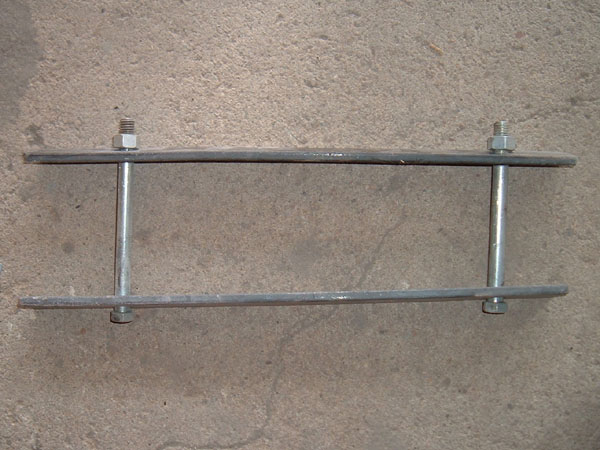
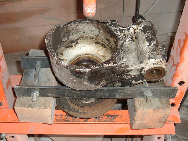
In order to press
out the wheel flange,
a “hub support” needs to be built (home made tool #
2). I made
mine by drilling two holes, one on each end, through two 12”
long
pieces of steel and then running bolts through the holes. The
hub
is then placed in between the two pieces of steel and the nuts on the
connecting bolts are snugged down. Each end of the
“hub support”
can then be placed on a block of wood to allow clearance to press out
the hub. NOTE I
recommend using
wood blocks rather than metal
to
support the hub because the hub is made of aluminum and, if the wheel
flange is stuck, you have less of a chance of damaging the hub if the
“hub support” is blocked up on something softer
than aluminum.
Once I had the hub correctly positioned, I placed a piece of pipe on
the inside end of the wheel flanges and a washer on top of it and
pressed out the flange. The outer bearing and seal will come out with
the wheel flange and can be pulled off by hand. The
inner
bearing
and seal can now also be pulled. The only parts left in the
main
body of the hub are the inner and outer wheel bearing
races.
These will need to be knocked out carefully using a punch. NOTE make
sure you are careful and that the hub is sitting on a wooden
surface such as a work bench, rather than a stone or metal surface,
because once again the hub is made of aluminum and can easily be
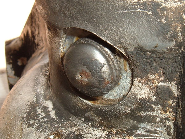
damaged. The last part to be removed from the
hub is the grease service
hole cap, which can be popped out with a screwdriver.
Hub support tool. when using it
hand tighten the
nuts. Never us a
wrench because cranking them down with a wrench could result in
damaging the hub. Also as previously mentoned us woden block
to support the tool when pressing out the weel flang.
Place a pipe spacer on the flang to press it out
Hub greaser plug needs to be removed from the hub
Hub and hub support blocked up on in the press to press out the wheel
flang
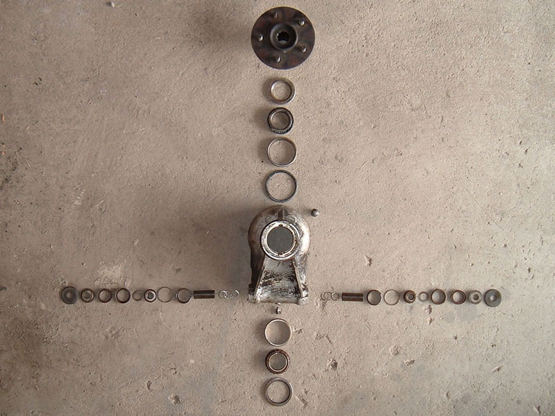
Exploded vew of the
parts that go in the hub
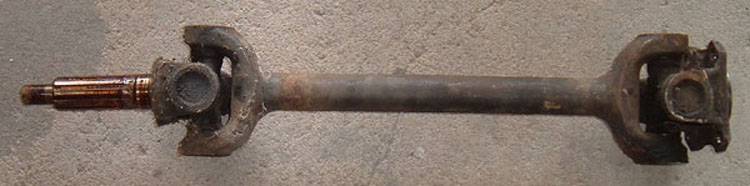
The only thing
left to disassemble is
the half-shafts. These each breakdown into three pieces
connected
by two u-joints. NOTE the
retaining clips that hold the
u-joints
into place are not typical u-joint spring clips, but rather snap rings,
and a set of snap ring pliers is required to remove them.
Once the snap
rings are out, the u-joints can be pressed out separating the three
pieces.
Now that
everything is disassembled
except the brake calipers and differential, all of the parts can be
cleaned. I recommend a good parts washer, a wire brush, a
putty
knife, lots of elbow grease and a blast cabinet if you have one. NOTE
if a part is marked with a Sharpie, make sure you clean it by itself
and then remark it since Sharpie marks wash off with most
solvents.
Once I have the
bulk of dirt and grease
scraped
off of any given part, I like using paint thinner as a metal
cleaner. It quickly cuts through the grease and is not as
pungent
or caustic as many of the commercially available parts cleaner fluids. NOTE
paint thinner will eat or
dry out most seals, plastics, and/or
other rubber parts, so do not use it to clean them. Also,
paint
thinner is highly flammable, so make sure you are not using it near
open flames, grinding sparks or welding.
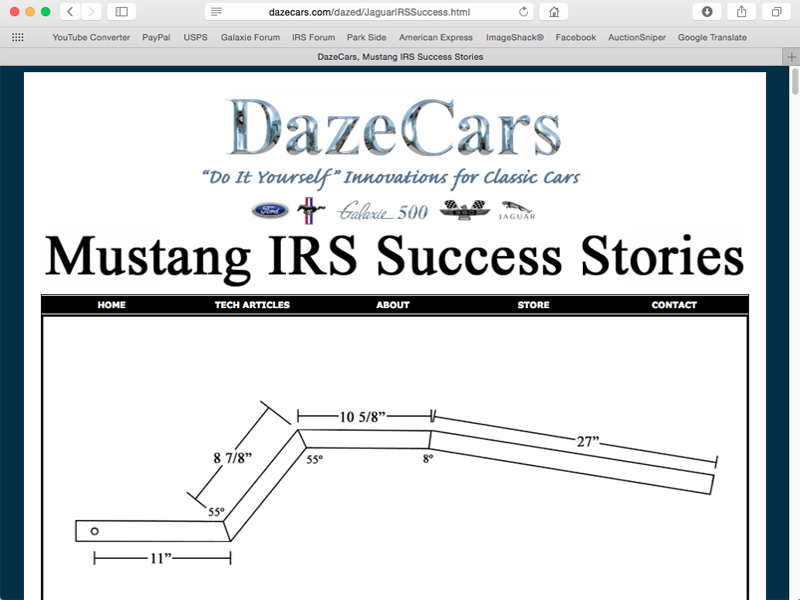
In the next article, page
III,
we
will look at narrowing of the LCAs and half shafts as
well as converting the Jaguar bolt pattern to a Ford bolt pattern.
BUT if you can't wait to see what a Jaguar IRS looks like
under a classic Mustang check out Mustang IRS
Success Stories
Disclaimer on Daze Tech Tips
I am not an expert
in this field. I have performed these modifications myself with very
good results. I am passing along restoration and
performance tips for the purpose of education. If you are
concerned about reliability or safety issues, I do not recommend that
you or any other individual perform these changes or attempt to modify
your cars from stock configuration except under your own
volition. I do not assume nor accept any liability for the
use of
this
information or how it is applied.


