Lokar parts are flashy and perfect for a hot rod, which is great if
that’s what you are going for, but I wanted something that
looks like
it was originally designed to be there between the seats of my classic
Mustang. The late model Mustang e-brake handle is a
natural
choice given its looks, functionality, and especially since there are
literally millions of Mustangs out there in bone yards with parts to
harvest. Also needed for this conversion are three
3/8"
fine thread grade 5 steel bolts, three 3/8" fine thread nuts, a 6" X 8"
piece of 16 gauge sheet steel, a 4" long piece of 1" X 1/4" steel bar,
an E-brake repair kit, two extra cable stops, an e-brake mechanism
cover, a three inch long piece of 1
&
1/2" angle iron and some nuts, bolts and oversized washers to use as
mounting hardware.
Process:
The first thing
I
had to decide was
"which stock Mustang handle was going to be best suited for my
application". Ford used two main styles of E-brake handle
between
1979 and 1993. The first can be found in Mustangs from years
79-86. This style is a good choice for those who are using
stock
drum brakes or disc brakes with a small E-brake return
spring. It
is a simple lever mechanism with no self-adjustment, so, if this handle
is used, all adjustment needs to be made under the
car. Also the
early type handle requires a hole cut in the transmission
tunnel.
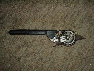
The second option, which is the one I chose, is to use a
stock 87-93
Mustang E-brake handle. There were several factors
that led to
this decision. First of all, in my humble opinion, the later
model handle is better looking and styled in such a way that it looks
right at home in a classic Mustang. The second reason I chose
this handle is that
it has a
self-adjusting mechanism with a tensioning
spring on it. That means that, once you get it initially set,
as
the cable stretches, the mechanism in the handle will make adjustments
to keep the E-brake consistent and functioning at optimal
performance. The only down side to this adjustment mechanism
is
that the return springs at the brakes need to be strong enough to
compensate for the tensioning spring and that means that it will not
work on drum brake cars with out modification.
NOTE
If you
want
to use the later model handle with drum brakes there is an option to
eliminate the self-adjusting spring. I will need to modify my
handle for an upcoming Jaguar
IRS install (week return spring) and will
add the process of modifying the handle after I have done so my self.
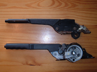
Unlike the 79-86 handle, by using spacers,
this handle can be installed
with out having to cut a hole in the tunnel. As you can see
in
the comparison picture, the two handles are quite a bit different in
both form and function. Once I made a decision as to which
handle
was best suited for my application, it was time to determine mounting
location.
When I made this
modification, I
removed my interior, including carpet and seats. Some
drilling is
required and, by removing these parts, I gained more working room,
eliminated the possibility of damaging my interior, and reduced the
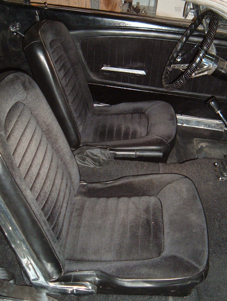
risk of a fire. After I removed my interior, I temporarily
reinstalled the driver’s side seat just long enough to get a
good feel
as to where the best location was for my new handle. On a 65
Mustang, there is a little hump on the transmission tunnel.
The
E-brake handle will either need to be mounted in front of or behind
it. I chose to mount mine behind because I am over
6’ tall and my
seat is always pushed back to the furthest point. In a
perfect
world, I would have liked to move my handle about 1” forward
so that if
I dropped my hand down it would naturally grasp the handle.
Unfortunately the previously mentioned hump in the tunnel prohibited me
moving the unit forward. It is important to keep in mind that
the
handle is off to one side of the mounting holes and a compromise will
need to be made between centering the handle and centering the mounting
points. While making this compromise, keep in mind that the
closer to center of the tunnel the handle is mounted, the further down
the slope of the tunnel the mounting bolts will be, which will cause
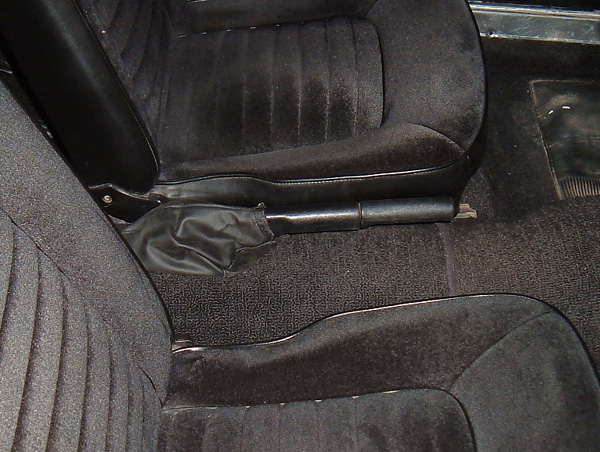
the handle to be mounted at an angle. I chose to mount my handle
slightly off from center towards the passengers side so as to minimize
the problem of it being at an angle. Other years of cars may require
other considerations in regards to the mounting location. The
next thing to deal with is reinforcing the sheet metal that is used to
make the trans tunnel.
The stock
configuration of the trans
tunnel is not strong enough to handle the pressure that will be applied
when engaging the e-brake. So to compensate I took
a piece
of 16-gauge sheet steel that was 6” wide and 8”
long and shaped it on a
large round piece of wood. I worked it tell I had a shape similar to
the trans tunnel, but bent the plate so the arc of the curve was just
slightly smaller than the arc of the trans tunnel. This was done so
that when everything was bolted together, the plate would be forced to
flex slightly by the curve of the tunnel and be held in place with a
small amount of compression. I checked fitment
often until
I had the fit I wanted. With the plate temporally in place I
used
the handle to mark on the plate where the mounting holes needed to be,
and then drilled the mounting holes in said plate. In the
process
of preparing everything for mounting I had another issue to
address. On the e-brake lever I used, the wheel hangs down
past
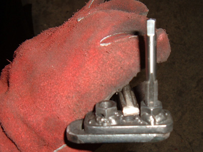
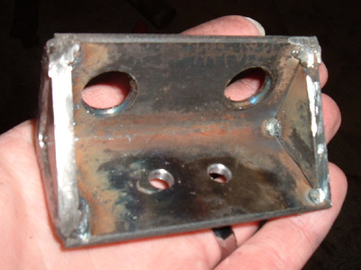
the mounting feet of the handle. In order to achieve proper
clearance between the tunnel and the wheel, I made two 1/4”
spacer
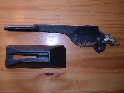
plates to be installed under the feet of the handle.

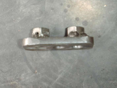
1/4" spacers and cable sleeve end |

Reinforcing Plate |
I positioned
the
plate I made earlier,
on to the tunnel in the place where it would be mounted and used it as
a pattern to drill the mounting holes.
NOTE brake and fuel lines
run inside the trans tunnel. Make sure you are aware of their
location prior to drilling so that you do not damage them.
Failure to locate their position could, at the very least, create more
work for you in having to fix them, and, the very worst, result in a
fire caused by leaking fuel. Once
the holes had been drilled, I
was able to mount the handle and reinforcing plate to the tunnel to
insure proper fit. The mounting hardware I used consisted of two bolts,
two nuts, two lock washers, two over sized washers for the underside of
the car, and the two previously mention spacers. I coated the
underside of the reinforcing plate with truck bed liner. This
is
a wonderful product to use on floor pans as its water resistance, sound
deadening and rust encapsulation properties make it ideal for this
application. I also had to drill a hole directly under the wheel for
the brake cable sleeve. The size of that hole was the same as
the
mounting hole for the e-brake fitting in the transmission crossmenber;
sense that e-brake fitting and cable sleeve were being modified for
uses between the handle and the rear brake cables.
-
As mentioned above
I had to fabricate
a sleeve for the cable that connects the e-brake handle to the rear
brake cables. This sleeve keeps the cable from rubbing on the
underside of the tunnel. I made one by modifying the stock front brake
cable sleeve that housed the brake cable from the transmission
cross-member to the engagement handle in the car. To do this I cut the
nub off of the end that originally went in to the transmission
cross-member so that it would be flat and would clear the wheel at the
new handle. Next step was to cut the sleeve to length and to devise a
means of fastening the cut end of the sleeve to a mounting bracket.
(piece of angle iron that would be bolted to the underside of the
tunnel) The new end was made by gluing a threaded gas line fitting
(1/2" threads) with JB weld to the end of the sleeve. This fitting is a
pressure fitting just like those used on Mustang break fittings only
bigger. I got mine from a piece of old gas line. To be able to attach
it to the angle iron, I cut a 1/2" nut in half and installed the
thinner part of it on the fitting so that I would have more surface
area on both sides of the mounting bracket. This allows it to be
inserted in to a 1/2" hole in the mounting bracket and the other half
of the nut tightened down. The sleeve was then wrapped in electricians
tape and sprayed with clear rubber to seal it. From there It was a
matter of inserting the “factory” end of the cable
up through a hole in
the tunnel and fastening it with a clip. On the other end the
angle iron bracket was bolted to the underside of the
transmission tunnel and the “brake fitting” end of
the sleeve was
secured in to place.
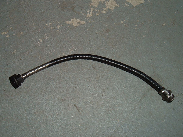
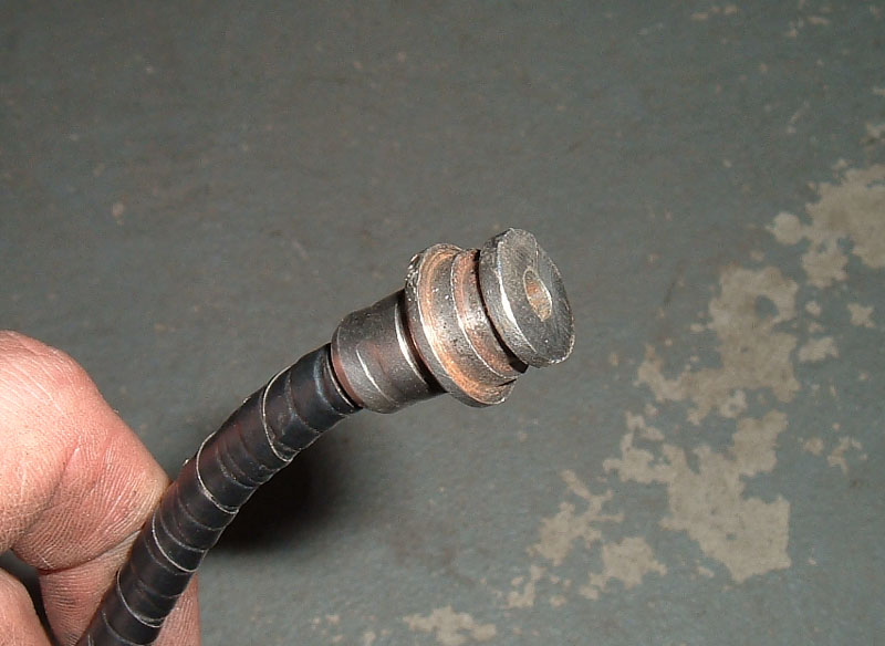
Modified Brake cable sleeve
|
Original end with tip cut off
|

End made with 1/2" pressure fitting |
| The
next step in
the process was coming
up with a way to converge the two stock brake cables into the one that
would be coming from the brake handle, as well as create a means of
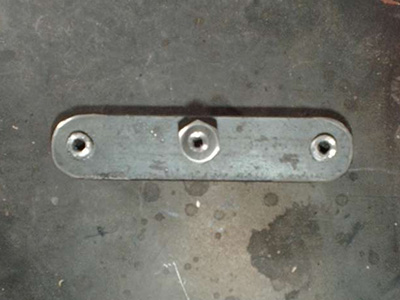
adjustment. I achieved this by fabricating a
bracket with
three threaded holes in it that hallow bolts could be threaded into, to
create an adjustable stop for the brake cable ends to pull
against. I cut a piece of 1" X 1/4” steel to a
length of 4” and
drilled three holes in it so that they could be tapped out to
3/8” fine
thread. NOTE
To use during the
taping
process, I fabricated a
tool that I call a “square tap” to aid in the
tapping of the
bracket. A “square tap” is a piece of
steel that has had a nut
welded to it. This gives you a tool that can be clamped to
whatever you want to tap and provides a guide that starts the tap
perfectly and squarely every time. Once all
three holes had been taped,
I turned my attention to the threaded sleeves. |
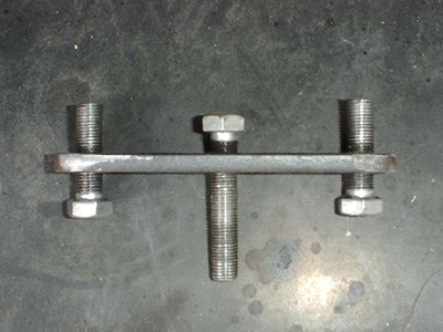
Convergence Bracket |
Square Tap |
Taping the bracket |

Drilling the bolt |
The adjuster
sleeves are created by
drilling holes all the way through three grade 5 bolts. I
accomplished this by affixing the bolts up through the hole in my drill
press. I had to modify a washer by grinding two sides flat so
that it would fit up in the underside of the drill press. I
then
put a washer on the topside and tightened the whole thing down with a
nut. This allowed me to drill the bolt out. The
middle bolt
in the assembly was going to have a smaller gauge cable passing through
it so I drilled it with a smaller drill bit. I then used a
larger
drill bit, the thickness of the stock cables, to drill out the two side
bolts. Once I had a hole all the way through the bolts, I
used a
step drill bit to enlarge the beginning of the openings so that it
would be easier to install the cable. The head of the bolt
was
also ground smooth so that the cable stops would not bind up on the
grade 5 markings as I turned the adjusting bolts. Once the
bolts
had been sufficiently modified, I threaded them into the bracket I had
fabricated in the previous step and turned my attention to the cable
stops.
Required
for this
project is an E-brake
repair kit, which can be found at your local auto parts
store. In
this kit are two essential pieces, one is a brake cable that will be
used to connect the e-brake handle to the convergence bracket, and the
other
is a cable stop. The hole on the cable stop is small and
perfect
for the cable in the kit, but far too small for the stock Mustang
e-brake cables. So I made two more of them, based in design
of
the one that came in the kit, only properly sized to accommodate
the larger Mustang cables. This was accomplished by buying
two
1/4” bolts, two 1/4” allthread couplers and two
small steel bearings
that were just small enough to fit inside the allthread
coupler. I took the couplers and welded one end
closed. I drilled a hole just above the sealed ends that was
the
correct size to accommodate the thickness of the Mustang e-brake
cable. Then a steel bearing was placed inside each of the
couplers through the 1/4" opening and the 1/4” bolt was
threaded into
the newly fabricated cable stop. The hole drilled through the stop
should be large enough to accommodate the cable but not so big that the
bearing can pass through it.
NOTE When a stop is slid onto a
cable, the
stop needs to be bolt side down so that the bearing rolls up against
the loosened bolt and opens the hole in the side for the cable to pass
through. When the bolt is tightened down, the bearing presses
into the cable and locks it in place.
At this point, I mocked up
the brake assembly to work out any bugs. As mentioned above,
I used the cable in
the
kit and threaded it through the cable sleeve I had fabricated and
mounted earlier, through the hallow bolt, and then into its
corresponding stop to attach the handle to the convergence
bracket. The stock Mustang cables were then installed in the
two
remaining sleeves on either side of the bracket. In the case
of
my car, some previous owner thought that rather than fixing the
emergency brake it made far more sense to just cut the
cables. In
the case of an intact E-brake system, the cable ends will need to be
cut off so that it can be threaded through the bracket. I
recommend cutting them long and then trimming them again after
everything has been assembled in the final stage. A cutoff
wheel
works well for making a nice clean cut without fraying the cable.
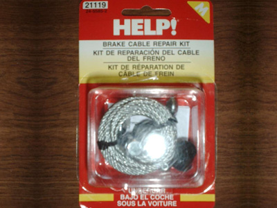
E-brake
repair kit with cable and stop
|
The top of the bolts have been smoothed off |
| A
"bug" I
encountered well testing was
that by leaving the original rear e-brake cables in the stock location
they were to far apart and the cable would bind up on the sleeve as it
left the cable sleeve, when the brakes were engaged and
disengaged. This was easily overcome by fabricating a bracket
that allowed me to relocate the mounting points of the stock brake
cables. I took a piece of angle iron, drilled two holes large enough to
mount the stock Mustang e-brake cables in, and than mounted the bracket
in the middle of the underside of the trans tunnel. I spaced
the
cable mounting holes with the same width as the convergence bracket so
that the two parts would line up with no binding of the
cable. I
also moved the mounting bracket towards the rear of the car to increase
the distance between the convergence bracket and the e-brake
mechanism. This gave me more room to accommodate the
convergence
brackets. |
brake cable mounting bracket |
At this point,
I
also ran two wires from
the E-brake mounting location along the trans tunnel to the
firewall. This was done so that I could utilize, in the
future,
the stock E-brake handle switch that indicates when the emergency brake
is engaged. Once I had all the bugs out I took the entire set up apart
so that I could install the carpet and then put the e-brake system in
one last time. After I installed the carpet, including mounting the
seat belt studs to hold the carpet in place, I installed the E-brake
handle and corresponding cable.
With the handle
properly installed, I
was able to turn my attention to the underside of the car.
Once again, the
single brake cable coming from the brake sleeve was threaded through
the middle bolt of the convergence bracket, and the cable stop was
installed but not yet tightened down. The stock brake cables
were
then threaded through their corresponding sleeves on the convergence
bracket. The bracket was moved to the rear of the car,
leaving
about 1” between the adjusting bolt and the ends of the brake
cable
where they protrude out of mounting bracket. The two cable
stops
for the stock cables were then installed and tightened
down. The next step took a little more trial and
error. I pulled the single remaining cable tight and
tightened
down its cable stop. I then crawled out from under the car
and
tested the handle. When it was first engaged and disengaged,
due
to the tensioning spring, the cable pulled forward but only retracted
about half the distance. It is this tension that creates the
self-adjustment. Upon further examination of the mechanism, I
realized that as the handle is pulled up, a small lever drops down and
grabs the teeth on the brake cable wheel. The further
backwards
the teeth are rotated and, thus, the further forward the arm grabs, the
less self-adjustment is remaining. More self-adjustment can
be
created by pulling more of the single cable coming from the handle
through the convergence block and relocating the cable stop, or by
turning the adjusting sleeves on the convergence block. I
chose
to do both. I first got as many teeth forward as I could by pulling on
the cable and then pulled the rest of them forward using the adjusting
sleeves. After all was installed and functioning perfectly, I then cut
the extra length from the cables, leaving enough extra for future
modification if necessary.
NOTE after
adjusting the e-brake
lever, make sure that when the lever is in the disengaged position that
the rear wheels turn freely. Failure to do so could result in
a
partial engaged e-brake system, which could potentially warp discs or
drums. All I had left was a few
minor details to deal with so
that I could complete this project.
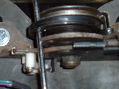
I found that if you rotate the wheel forward you can push a screwdriver
in front of a notch on the wheel to hold everything in place while
hooking it up under the car. |

When I pulled the handle the first time, the drop down arm grabbed the
teeth about half way up. When I released
it,
the tentioning spring held the mechanism with most of the teeth rotated
back. |
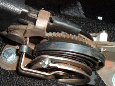
Due to the proper functioning of the
self-adjusting mechanism, the drop down arm is grabbing at the last
tooth so I had to make
adjustments under the car to increase the amount of "self-adjusting"
teeth.
|
One thing I
initially overlooked, but
remedied very quickly after I discovered it, was that when I relocated
the stock cables they had the potential to rub on both the bottom of
the car, as well as my fuel and brake lines. This issue was
quickly remedied by splitting two 18” long pieces of rubber
hose and
then sliding them over the brake cables from a point just behind my
mounting bracket all the way to where they pass through the frame, and
then fastened them in place with zip ties. Another issue I
had to
deal with was that my vent opening knob was held into place by the same
bolts that held the original e-brake handle in place and the nuts that
the bolts threaded into were actually part of the brake
handle.
This was remedied by simply cutting off the mounting end of the
original e-brake bracket and putting it back in the car where it was
originally designed to go, that way I had something to screw the bolts
up into. The last issue I had was in covering the brake
handle
mechanism. I had hoped that an E-brake handle cover from an
86
car without a console would have fit but after buying one I realized
that it was too small, however, it is the perfect option for anyone
using the earlier style 79-86 brake handle. What I ended up
using
was a vinyl manual transmission shift boot for a modern Ford
car.
Unfortunately, I have no clue what car it came from. I bought
it
from eBay and the seller was unsure what car it was for.
All in all, this
was a good project and
I am extremely pleased with the result. However, due to the
amount of troubleshooting required on this project, I would say that it
was one of the more difficult modifications I have performed,
especially before I realized how the self-adjusting mechanism on the
e-brake handle worked. I hope that the information I have
provided will help eliminate any troubleshooting you may encounter if
you attempt a similar project on your own vehicle. If you
have
any questions or comments, please feel free to send me an
email.

Convergence bracket and cable mounting bracket |

Cable sleeve installed under car |