Bolt-in
Spring
Compressor / Ball Joint Removal Tool When
working on a
classic Ford, many
repairs/modifications can be done using basic tools, however, sometimes
a specialty tool is required for said repair or modification to be done
correctly and/or safely. Many front suspension modifications may
require the use of two such specialty tools: a non-damaging ball joint
removal tool or a spring compressor. Both of these tools can
easily be built at home using just a few basic tools and skills.
Spring
Compressors 101, Why use a
bolt-in
type? When
removing a coil spring, it is
required to compress the spring to free it from its designed location.
Failure to safely deal with compressing the spring can result in
serious injury or even death. There are three main ways to
compress a coil spring to remove it: external claw type spring
compressor, internal claw type spring compressor or a bolt-in type
spring compressor.
An
external claw
type spring compressor
consists of two separate pieces that clamp onto the outside of the coil
spring. As the nuts on the two pieces are tightened down, the
spring is compressed. There are three main issues with this
type
of compressor. First, both sides need to be tightened an
equal
amount and, since each piece has its own tightening nut, this is easier
said than done. Second, this type of compressor REQUIRES that
the
two separate pieces be opposite of each other. Unfortunately,
the
shock towers of a classic Ford do not allow the two pieces to be
positioned completely opposite of each other, which creates an unstably
compressed spring. Third, the claws of the compressor are
held to
the spring by tension from the compressed spring. If the
claws
slip, the spring can decompress violently. Many chose to use
this
type of compressor because they are inexpensive and can be purchased
for less than $30.00.
The second type of
claw spring
compressor is an internal unit, which has four claws (two at the top
and two at the bottom) that grab an upper and a lower coil of the
spring. One tightening nut pulls the two sets of claws closer
together and compresses the spring. This compressor is much
better for a Mustang than the above mentioned external claw type,
however, it is still not the best option. There are two main
problems with this type of system. First, often times on a
classic Ford, a 3 to 4 inch spacer (usually a piece of pipe) is
required to be positioned between the upper claw assembly and the
tightening head to keep the compressor from bottoming out in the
UCA. Secondly, as with the external claw type, the tension of
the
compressed spring is all that holds the compressor in place and, as
before, if those claws slip, the spring can decompress violently.
It was an
internal
claw type compressor
that sent me to the emergency room in June of 2005. After
already
removing the passenger’s side spring, I was working on the
driver’s
side assembly, had compressed the spring and was in the process of
removing it when the compressor slipped, the spring decompressed and
pinned my right hand by the three middle fingers, palm side up, between
the bottom of the coil spring and the spring perch. Engaging
this
type of compressor requires using two hands and, of course, I was
alone, the garage door was down, my cell phone was on the
passenger’s
side fender out of reach and most of my tools, at least any that could
have been effective in freeing my hand, were on the floor next to the
passenger’s side where I had already pulled the suspension
apart.
All I had within arms reach was the 1⁄2” box wrench
(no more than
6” long) that I had just used to remove the shock.
I jammed the
wrench in between the spring and the perch and was able to pry the
spring up enough to get the finger next to my pinkie free. I
then
pried on the opposite side and got my index finger free. To
get
my middle finger out, I pried again with the wrench and pulled as hard
as I could with the trapped arm and got my hand out. To make a long
story short, I still have all my fingers and they still work, however,
I occasionally feel some stiffness in the middle finger
joints. I
was lucky!!!!! Needless to say, it is my personal mission to
convince everyone to use a bolt-in type compressor.
The third type of
spring compressor is
the previously mentioned bolt-in type compressor. This
compressor
bolts to the spring perch and the top of the shock tower, just like a
shock. Once the spring has been compressed, there is no way
for
it to come loose unless you intentionally decompress the
compressor. The “down side” to this type
of compressor is that in
order to completely remove the spring, the UCA needs to be removed to
get the spring out. This adds about 15 minutes to the task of
changing springs, however, that 15 minutes is well worth the improved
safety factor.
Before
you start this project you need to evaluate your welding
skills.
Before
you start either of these projects, you need to evaluate your
welding skills. The following is the process for constructing
a
tool
that will be holding immense amounts of pressure and, if your welding
skills are not sufficient for the task, the tool could fail which could
cause harm or even death. NOTE:
If you have any
doubts AT ALL
about
your welding skills, DO NOT ATTEMPT TO BUILD A SPRING
COMPRESSOR!! One
option for the non-welder is to prep the parts and then take them to a
certified welder for assembly.
Materials
needed:
.625”
coarse thread
all-thread, 12” long, grade 8 (non-galvanized)
.75” square tubing, .0625” walls, 9” long
1” X .25” X 3” bar stock
1.5” X 1⁄4” X 3” bar stock
.625” coarse thread nut, grade 8
.625” grade 8 washer
two .375” X 1” grade 8 bolts
two .375” grade 8 nuts
two .375” grade 8 washers
shock, spring perch, coil spring to get measurements from
Tools
required
for the project:
Cutting tool
Welder
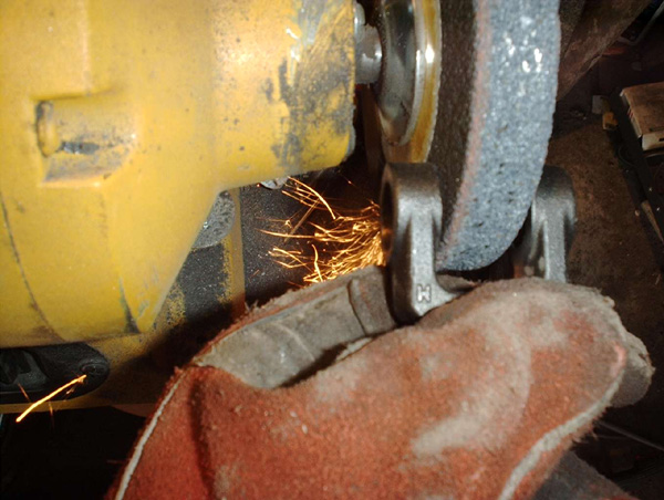
Drill bits and drill
Bench grinder
Materials needed
Cutting the All-thread
All-thread sand blasted end
Prep
the materials:
The
first
step is to prep all the
parts needed to assemble the compressor. It is good to have a
shock and a spring perch on hand to ensure fitment as pieces are being
fabricated. Start by cutting a piece of coarse thread, grade
8
all-thread to a length of 12”. NOTE: It is important that
you use all-thread that has been treated with black oxide as a rust
preventative, rather than galvanized all-thread because as pressure is
applied to the galvanized threads during the compression of the
springs, the galvanization will come loose and clog the threads in the
nut, which decreases the functionality of the compressor.
Once
the all-thread has been cut, it needs to be cleaned on the end that is
going to be welded. If you have the opportunity to use a sand
blaster to strip it down to bare metal, you will get better weld
quality.
The next step is to
cut the .75” square tubing to a length of
9”. For best welding, one
end of the square tubing needs to be drilled out for plug
welding. Measure down .5” and then drill a
.125” pilot hole
completely through the square tubing. The .125”
hole then needs to
be enlarged to .5”.
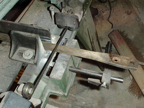
It is now time to cut
the
base plate. This piece measure out at 1” X .25” X
3” and needs to
have two .475” holes drilled with a spacing of
2.125”. Once
the holes are drilled, the corners need to be rounded and the underside
on both ends needs to be beveled so that either end can fit easily in
position on the perch. I recommend trying the plate on a
perch to
ensure functionality. NOTE: older perches have a
tighter
fit than aftermarket ones so use an older original type perch to check
fitment and have a more universally functional tool.
The
last piece to prep is the shock tower cap. Cut the cap
retainer
so that it measures 1.5” X .25” X 3”,
drill 2 elongated holes so
that the cap can be bolted to the top of the shock tower (the
dimensions for these holes can be obtained from the top of a
shock). Then drill a .625” hole in the center of
the plate so that
the all-thread can come up through the middle.
Cutting the square tubing
Plug weld hole in square tubing
Base
plate with .475" holes
Beveled
edges on base plate
Shoct
tower cap
Now
that the pieces have
been prepped, it is
time to assemble the compressor. The first step is to thread the
cleaned end of the all-thread 1” into the end of
.75” square
tubing with the hole. Due to the .5” plug weld
holes, the
all-thread should actually need to be threaded into the square
tubing. Once the all-thread has been threaded in, the easiest
way
to hold it in place and square it up is to tighten a nut down onto the
end of the tubing. Make sure you only hand tighten the nut
because the metal on the inside of the tubing that causes you to thread
the all-thread in is not strong enough to cope with the pressure of
tightening the nut down with a wrench. It is now time to weld
the
1⁄2” holes closed. Once they have been
welded shut, the lip
of the square tubing needs to be welded to the all-thread.
After
welding, you should be able to look at the threads on the all-thread
and see penetration where the threads have melted during
welding. NOTE: If
this penetration can not be seen after welding, you may
want to question the quality of your welds and reconsider having the
parts professionally welded together.
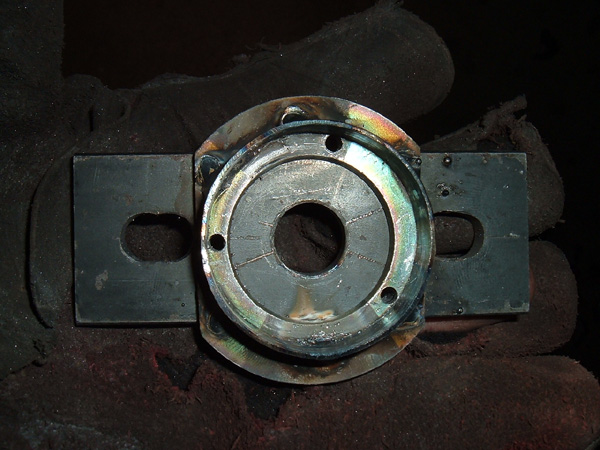
The base can then be welded
into place, making sure it is centered, square, and that the welds have
good penetration. At this point, the majority of the
compressor
has been fabricated and it is a good time to test fit the base to a
spring perch again to ensure proper fit.
Once
you have a
good fit on the spring
perch, install the .475” bolts into the holes already drilled
in the
base. When I fabricated my spring compressor, I happen to
have
press-in studs so I used them. If I had not had press-in
studs, I
would have held the bolts in place by tightening a nut down onto
them. The heads of the bolts can now be welded to the
base.
The last thing we need to do to complete our spring compressor is to
finish fabricating the shock tower cap that we have already cut to
length and drilled several holes in. There are two options
available to complete this piece.
All-thread
inserted in square tubing
Hole
plug welded closed
Weld
penetration in threads
Base
spot welds
Base
welded on
Press
in studs
Studes
welded in place
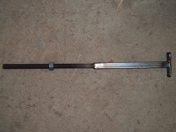
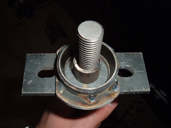
Completed
assembly less the cap
The
first
(simpler) option is to make a
dual washer cap. This cap bolts into the top of the shock
tower,
just as the shock did. Since the cap has already been drilled
with three holes, a .625” washer needs to be welded to the
middle of the
cap over the 5/8” hole. You can grease the face of
the washer,
place another washer on top and then the tightening nut goes on top of
that. The two washers then press against each other and slide
as
the nut is tightened down.
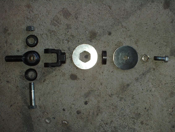
The
next option is more complicated but
makes a much better functioning tool, which is to use a tapered bearing
in the top. The first step is to obtain a tapered roller
bearing
and race by either buying one new or removing one from a wheel hub
assembly that is not being used. I got mine from an old disc
brake assembly I had removed from a 1984 Mercury Grand Marquees I had
parted out some years back. It was the outside bearing and
its
measurements were an I.D. just over .75” and an O.D. just
less
than 1.75”. The first obstacle to overcome is that
the
bearing hangs down past the race. I found a low profile
1.5”
washer, cut the ends off to clear the mounting holes and welded it to
the cap plate, making sure it was centered over the .625” cap
plate
hole. To center it, I took a .5” washer that was
snug fit
inside the 1.5” washer and drilled the hole out to
.625” so
that I could
bolt it to the cap to center the outer washer. I then found
some
exhaust pipe that had an I.D. 1.75” where the race was a
nice tight fit inside. I cut a .575” ring of this
pipe and
welded
it to the top of the washer I had just attached to the retainer
cap. Three holes were drilled along the inside edge of the
ring
so that if the race needs to be removed it can be tapped out with a
punch. Once the holes are in place, the race can be pressed
in. At this point the cap is basically done but there is one
more
issue to overcome. The all-thread for the spring compressor
is
.625” and the I.D. of the bearing is .75” so, to
fix this,
I cut a
spacer ring out of some .625” steel pipe I had and ran a
drill
bit
through it to clean out the seam so it could slide nicely over the
all-thread. This spacer was the last piece needed.
Non
bearing shock tower cap
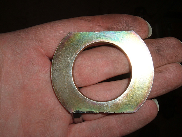
Low
profile washer used to create bearing clearance
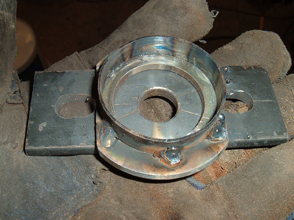
Retainer
ring
Race
removal holes
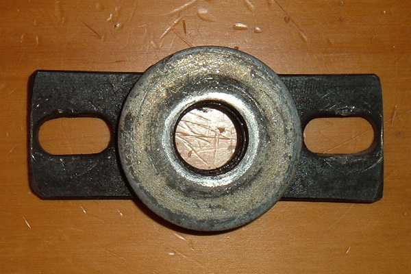
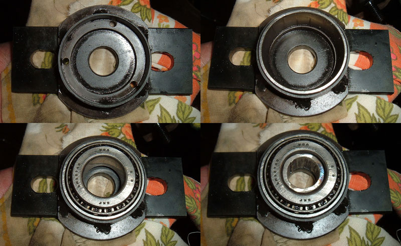
Installed
race and spacer
The final step
to
finish the tool is to
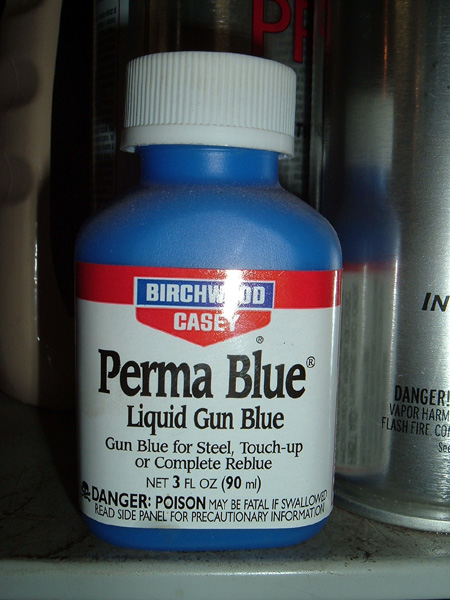
clean it up and coat it with a rust preventative. This is
accomplished by sand blasting the spring compressor parts, except the
bearing and race, and then coating them with Gun Bluing. This
simple compound that can be purchased at many sporting good stores and
is similar to black oxide. The compound needs to be heavily
applied to the metal and then allowed to dry. Once it is dry,
the
metal will have a brown/green look. I then wipe it down with
a
dry rag to prep it for oiling. Oil or grease can be applied
with
a soft rag and, as it is applied, the metal will take on a blue/black
color. This type of protection will not make the tool rust
proof
from direct water contact but it will eliminate flash rust. NOTE: paint is not used to protect the
tool because it will clog
up in the threads and will tend to be eaten by anti-seize oils applied
to the threads during use. The compressor is
now completed and ready to
use.
To
use the
compressor, simply remove the
shock and bolt the base of the compressor to the spring
perch.
Then slide the cap over the all-thread that sticks out the top of the
shock tower and bolt it in place. Apply a small amount of
anti-seize oil to the threads that protrude out of the shock
tower. The bearing, spacer sleeve, cap washer, and tightening
nut
can then be installed and tightened down which compresses the
springs. The spring should not need to be compressed more
than 3”
to work on suspension. Once the spring is compressed, the
spring
perch can be unbolted from the UCA and the UCA nuts can be
removed. NOTE: if your
car uses shims to do the alignment,
remove them and mark them so that they are put back in the same place
during reassembly. The UCA can now
be removed and the tension can
be slowly taken off of the spring by loosing the retainer nut, making
sure that it does not hang up on anything as it expands. Once
all
the tension is off, the spring, compressor and spring perch can be
removed from the shock tower as a unit. To reinstall springs,
follow the above directions in reverse order.
Gun
bluing compound
Here are 4
shots showing the instilation of the race, bearing, and spacer in to
the spring compressor cap.
One bolt in
spring compressor complete with bearing cap
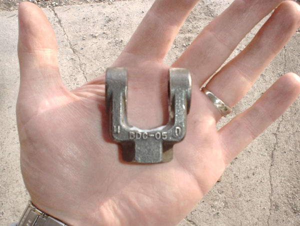
Ball
Joint Tool
Separating
Ball Joints
Separating ball
joints from the spindle
can be a challenging task, especially when the two parts have been
together for a long time or you do not want to damage the ball
joint. For many years, the standard for separating the ball
joints from a spindle has been the pickle fork and/or a
hammer.
These tools can be effective but can also be very damaging to ball
joints. A much better option is to
“press” the ball joint stud
out of the spindle using a press tool. I originally received
a
picture of this tool from MustangSteve of www.MustangSteve.com.
Using MustangSteve’s design, such a tool can be easily made
using just
a few simple tools and a few inexpensive materials.
Materials
needed:
two
.75” bolts
one .75” coarse thread, all-thread coupler
or
.75” coarse thread, all-thread
two .75” coarse thread nuts
one .75” coarse thread, all-thread coupler
three .1875” press pins
Tools
required
for the project:
Cutting tool
Drill bits and drill
Welder
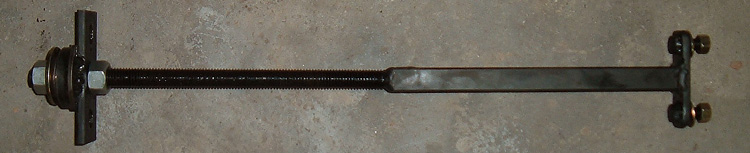
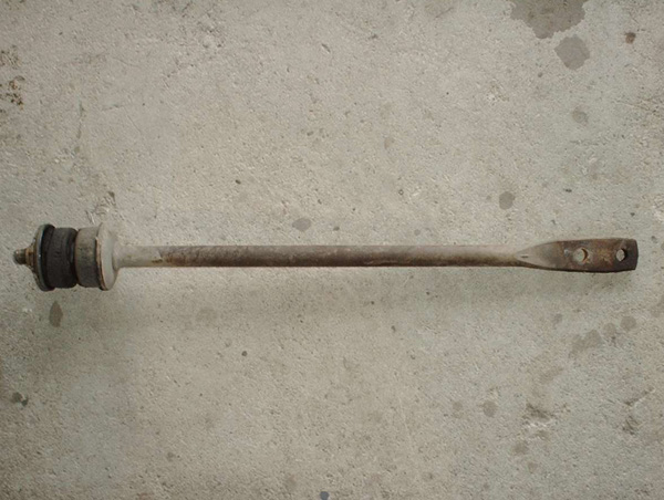
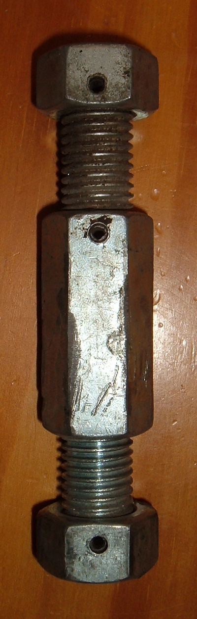
Ball
Joint
Removal Tool
There are two ways
to make this
tool. The first is to thread two .75” bolts into an
all-thread coupler. The advantage to this is that you can
purchase several different length bolts so that the length of the tool
can be modified to work on different spindles. The
disadvantage
is that there is nothing other than pressure to hold the bolt heads to
the ball joint studs. A better option
IMHO is to
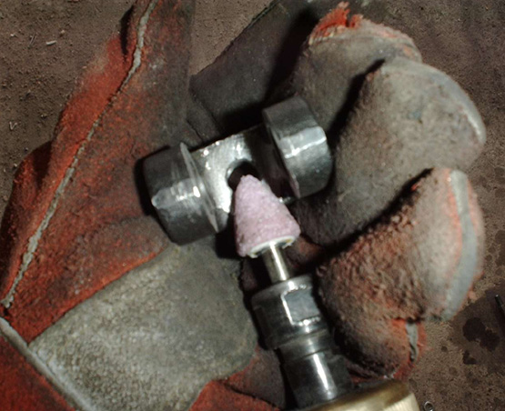
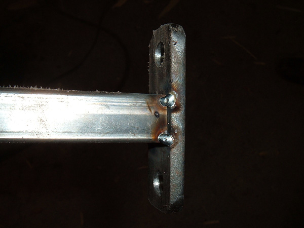
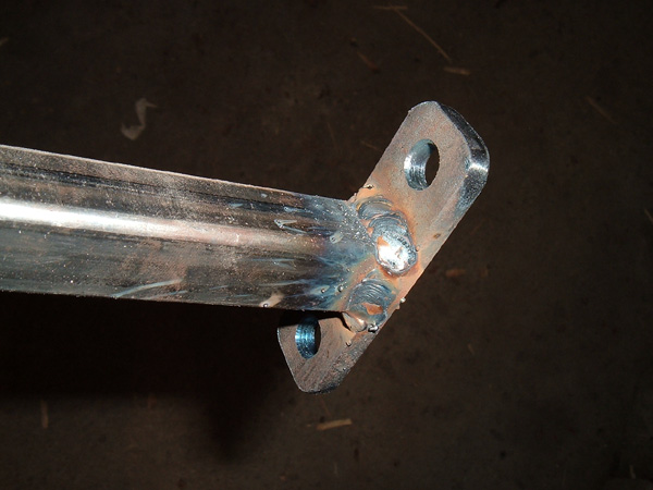
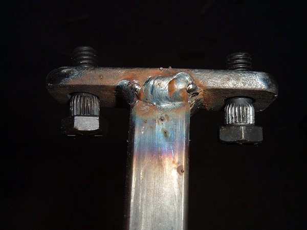
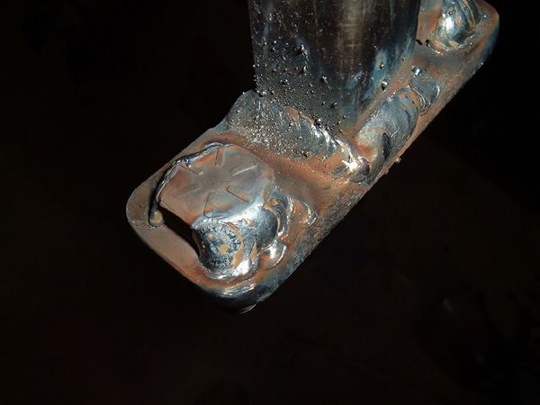
attach two nuts to some all-thread, either by press pins or by welding.
Using nuts gives you a little cup at the top and bottom of the tool for
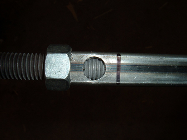
the ball joint studs. I fabricated my tool by cutting two
3”
pieces of all-thread, threading a nut onto the end of each one, leaving
about .125” depression, then drilled and pinned the nuts to
the
all-thread. I then inserted one of the all-thread/nut pieces
into
the all-thread connector and drilled it and pinned it in
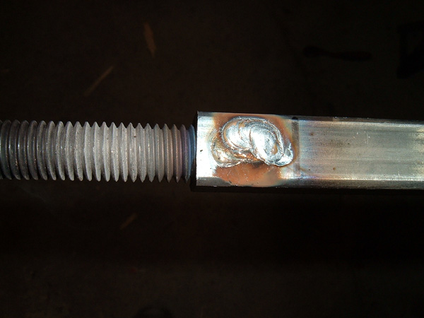
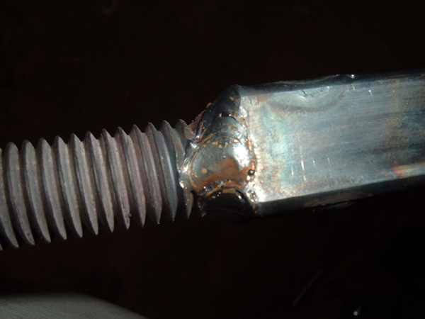
place. It is just as effective to weld the nuts and
all-thread connector to the all-thread rather than pinning them,
however, I chose to pin them for a cleaner looking tool. Once the tool
has been built, using it is quite simple. Pull the ball joint
retainer pins, loosen both nuts about .125”, install the tool
and begin
to expand it by holding the solid end and unthreading the removable
end. As the tool expands, pressure is applied and both ball
joint
studs should pop out of the spindle. At this point, the nuts
can
be removed and the spindle can be removed.
Ball Joint tool
Disclaimer on Daze Tech Tips
I am not an expert
in this field. I have performed these modifications myself with very
good results. I am passing along restoration and
performance tips for the purpose of education. If you are
concerned about reliability or safety issues, I do not recommend that
you or any other individual perform these changes or attempt to modify
your cars from stock configuration except under your own
volition. I do not assume nor accept any liability for the
use of
this
information or how it is applied.