The concept of putting a bearing in the classic Ford spring perch was
first introduced by John Dinkel. He invented them and I give him
all the credit. Over the years he and I have become friends as we
both have the same goal of making classic Mustangs handle better.
The following article was written with his blessing so that anyone who
wants to make a set of roller spring perches has the info needed to do
so..Many Ford cars, from
the Falcon to the
Granada, use spring perches bolted to
the upper A-arm that serves as a bottom resting point for the coil
springs. The design of the spring perch, through its ability
to
rotate
back and forth as the A-arm travels up and down, allows the coil spring
to move with more consistent vertical travel through compression and
decompression.
The original spring perches found on the early
Falcons
had brass bushings. This allowed for a smooth
rotation but
had the
downside of needing regular greasing and considerable friction
between the surface of the bushing and the journal it rested
in.
Sometime before the Mustang hit the market in 1964, FoMoCo
decided to
replace the brass bushings with rubber ones, which was done primarily
to
cut
costs. Although cheaper to produce, the rubber
bushing
spring perches lacked
the
smooth, easy turning radius afforded by the brass
bushing.
If you
have
ever tried to turn the center shaft in a rubber bushing spring
perch,
you know that it takes quite a bit of force to get any
movement. One
might argue that a coil spring provides all the pressure
needed
to turn
the perch and that a smooth turning radius is not necessary, but the
problem is
that the force applied, from suspension travel, to move the perch prior
to the rubber bushing flexing is absorbed by flexing of the spring and
shock. This flexing of the spring and shock results in a
less than consistent, less-vertical travel during compression and
decompression, and thus puts a lot of stress on the shock, making it
wear
out sooner. One option in correcting this
issue is to replace the rubber bushing with aftermarket brass bushings,
returning the perch to the initial Ford design. This works
well,
but without regular greasing, brass bushings tend to squeak.
Another option is to create the roller spring perch. By
replacing
the rubber bushings with roller bearings, a smooth turning radius can
be
achieved and, thus, smoother suspension and drivability without the
added friction and squeaking of a brass bushing. The
following is
the step-by-step documentation of how I fabricated my own pair of
roller spring perches. This could not have been possible if
it
had not been for the advice and directions from the original designer
of the roller spring perch. He is a Mustang builder, racer,
fabricator, and regular on several Mustang message boards including FYI
Ford, and goes by the screen name of
“Opentracker”.
MIG
or TIG welder, 2” bie-metal hole saw, drill press, saw for
cutting
pipe, die grinder with grinding stone and sanding wheel, brake hone,
deep 7/8” impact wrench socket, ball pein hammer, punch,
bench grinder
with wire wheel, vice grips, pipe centering block, pipe holding tool,
1” long piece of 3⁄4” square tubing, and,
ideally, a shop press.
Hand tools and
centering and pressing jigs
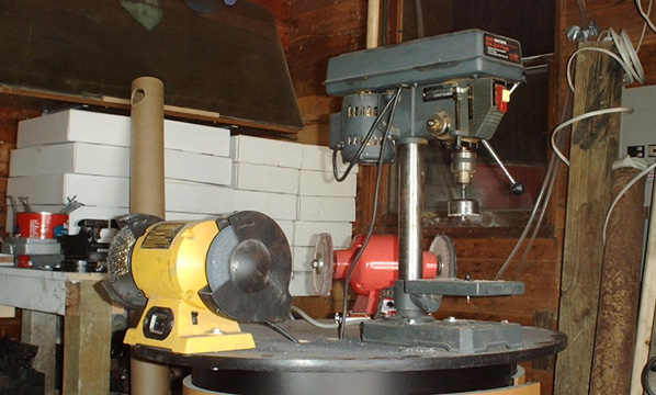
Drill press and bench grinder
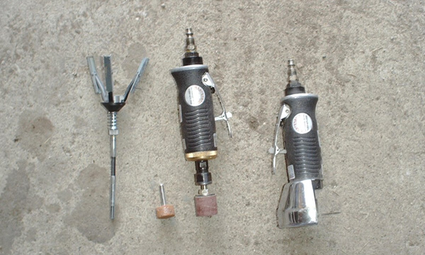
Brake hone, die
grinder, and cutting wheel
Materials
required:
Two
modifiable spring perches in reusable condition with mounting hardware,
(some aftermarket spring perches use metric shafts that are to small to
fit snugly inside the bearing)
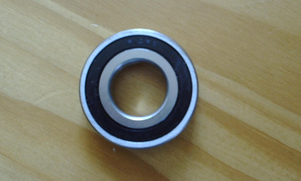
four HIGH QUALITY R14-rs type bearing 7/8” ID and
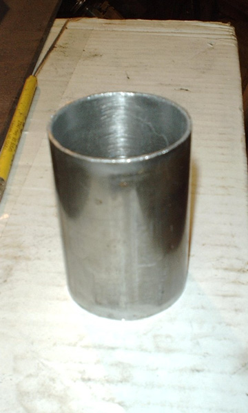
1&7/8” OD, and
two 3” long
pieces of 2” OD pipe with 1/16” walls. Roller
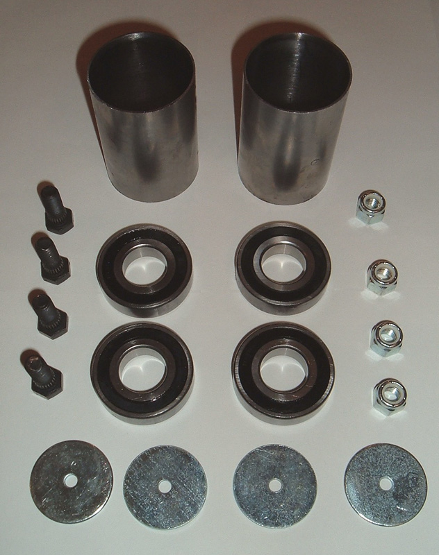
Perch rebuild kits for sale: I
have for sale all the parts you need to convert stock or aftermarket
spring perches to roller spring perches. This kit includes two 3" long
honed and fitted bearing journals that are ready to weld into the
perches, four high quality R14-2RS bearingss, four press in
mounting studs, four locking nuts, and for centering washers to drill
out the perch body. Click
here to
order
bearings, journals, or complete kits.
Note:
Some aftermarket perches use metric shafts which are to small to fit snugly inside
the bearings. I use ACP brand aftermarket perches or OEM cores as they have the correct shaft size.
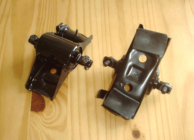
Process:
The
first thing to start with is a pair of stock spring perches.
Aftermarket reproductions can be purchased or the ones currently in the
car can be removed so that they can be modified. (Always use
extreme
care when compressing and removing coil springs.) If using
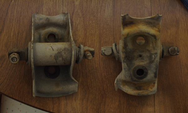
the
original
perch, make sure that it is in reusable condition. Examine
the
center
shaft mounts and make sure they are not in any way damaged, cracked, or
bent, also examine the main body of the perch for cracks
and/or
breakage. Once the spring perches have been determined to be
a
sound
platform for modification, the process can begin. The first
step
is to
remove the mounting studs that are pressed into the main
shaft.
This
can be easily done by placing a small piece of 3⁄4”
square tubing
approximately 1” long under the main shaft so that the
threaded side of
the stud is up and the head of the stud goes down through the middle of
the square tubing, and then by using a shop press, simply push the stud
out. If you do not have a press, you can put a nut on the end
of
the stud and tighten it down so that the edge of the nut is flush with
the
end of the stud, and then drive the stud loose with a hammer.
Once the stud is loose, the nut can be removed and then the nut and the
stud can be set
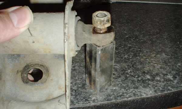
aside for later use. The next step is to take a
cutting
wheel and cut
down through the side of the main perch body along the edge of the
center shaft tubing. By doing this, the entire
shaft
assembly can be
removed in one piece. Set the shaft assembly aside for
further
deconstruction later in the process.
The
current mounting points for
the center shaft assembly will need to be cut away to make room for the
larger bearing journal that we will be building. Two washers,
one
on
each side, will need to be spot welded to the main body of the spring
perch. The purpose of the washer is to provide a centered
pilot
hole
for the 2” hole saw that is used to cut away the
side of the
spring
perch. I found that getting a washer with a center
hole
that is just
smaller than the pilot drill bit on the hole saw helps to achieve a
more
uniformly cut perch. Also, the washer needs be
moved about
1/16” down
from the top of the spring seat, which is done so that the new
bearing
journal can be mounted into place and still clear a small hump in the
inside middle of the spring perch. Take special care to make
sure
that
the washer is well centered from side to side, this will make for
easier assembly later. Use a drill press and a 2”
bie-metal hole
saw
and drill out each side of the perch. Be careful when
drilling
not to
apply too much pressure. Without the center assembly intact, the
sidewalls of the perch are not very well supported and can bend under
excess force. However, if the sidewalls do bend some during
drilling,
they can be straightened with a pair of pliers. It is a good
idea
to
test fit the pipe that will be used as the bearing journal.
It is
important that the pipe fit squarely in the perch. If it sits
at
an
angle, a die grinder can be used on the sidewalls of the spring perch
to
remove any metal that is preventing the pipe from sitting squarely in
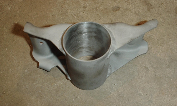
the perch. Once both sides have been drilled out and checked
for
a
square fit, there is not much left of the original perch, however, what
remains is a solid platform for the improved perch. The
center shaft will now need to be removed from the center
assembly.
This is accomplished by making several cuts the length of the assembly
with a cutting wheel. Once you have cut through the metal,
the
rubber
underneath is no match for a cutting wheel so be extra careful not to
cut into the main shaft. If the perch being
modified is an
original,
then the shaft should be relatively easy to remove from the center
assembly once the case has been split. However, if the
perches
are
new
aftermarket pieces then the removal of the center shaft will be more
difficult. A long 1/8” drill bit can be used to make lots of
holes
through the rubber all the way around the center shaft. This
will
not
completely free up the center shaft but it will make its removal much
easier. (When drilling down through the rubber, pay special
attention
to not damage the center shaft with the drill bit.) After
much of
the
rubber has been drilled out, the outer covering can be pealed off of
the center shaft by grasping it with a pair of vice grips and
pulling.
Any remaining rubber that is adhered to the shaft will need to be
cleaned off with a wire wheel. Once cleaned the shaft can be
prepared
for the bearings. For
optimal strength, the bearings will need to ride in the bearing journal
directly in line with the sidewalls. My measurements
indicated
that the inner edge of the bearing would be about
15/16” from
the
outside edge of the shaft. You will need to take your own measurements
because there is often times some variation in parts. The next step is
to use a punch to
dimple
the main shaft. This gives a slightly enlarged area for the
bearing to
press onto and rest against. The easiest way to get a uniform
line of
divots around the shaft is to take at least three raps of
electricians tape around the end of the shaft so that there is a
clear indication of where to punch. The build up of the tape
forms a
lip that the point of the punch can rest up against. The
shaft
should
then be put in a pipe centering block and the divots can be placed on
the shaft about 1/8” apart with a punch and hammer.
If you do not
have
a pipe-centering block, you can buy one or make one. I made
mine
by
welding three pieces of angle iron together in the shape of an
“M”. If you have a press you can also
make four divots about 1/4"
from the line of divots you just made, one on the top, the bottom, and
on both sides. Theses divots are positioned so that the
bearing
will be pressed over them this will hold the bearing in place more
firmly, but can only be done if you have a press.
CAUTION
trying to force the bearings over the four divots with out the use of a
press could result in bearing damage and premature failure. It
is now time to press the bearings in place. A deep
7/8” socket
works
very well for this. When pressing on a bearing you want to put the
pressure on the inner race. If pressure is applied to the
outer
race,
then damage may occur to the bearing. Place the socket on the
press
and then set the bearing on top of it. The shaft can then be
slid
down
into the center of the bearing and into to the socket. Pressure can be
applied to the top of the shaft to seat the bearing. The
bearings
need
to be pressed on so that only about 1/3 of the width of the dimpling
can be seen. This holds the bearing in place but still gives
it
something to rest against so that in later steps the bearing is not
pushed further onto the shaft. If you do not have a press,
the
bearing
can be seated with several light hammer blows to the top of the shaft,
being careful not to damage the shaft. Once the first bearing
has
been
seated, the shaft needs to be turned over and the same steps are used
to
seat the second bearing. If in the process of seating the
bearing, the
shaft mounting holes become ever so slightly out of round, that is not
a
problem because it will help hold the mounting studs when we
press them
back in. However, if the hole becomes very elongated it would
be
a good idea to
replace the shaft. Excess bending at the boltholes could
cause
cracks
and/or brakeage at some time in the future. Next the bearing journal
should be
prepared. Measure the distance
between the outside edges of the bearings on the shaft. The
journal
will need to have between 1/8” and 1⁄4” of
material past the
bearings on
each side. The bearing distance (outside to outside) on this
set
of
perches measured at 2&5/8”, so I cut my pipe
3” long . This
gave me
a little bit of extra tubing just in case I needed to square things up
with the grinder or a file. When cutting the pipe, it is best
to
use a
chop saw or a band saw, that way you get a good square cut. A
hacksaw
will work, but be careful so that the cut is square. Do not
use a
clamp-on pipe cuter!! I am talking about the type of cutter
that
clamps itself to the pipe and then you spin it around the pipe until
the small wheels to cut through. The reason you
don’t want to use
that
type of cutter is that it will taper the edge of the pipe inward,
making the hole too small for the bearings. Once
cut, the
pipe can be
checked to make sure that the cuts are square. If square, it
is a
good
idea to use a flat metal file and clean up the leading edges, also a
round file works very well to remove any inside lip that might have
been created from cutting, grinding, and/or filing. The
bearings
should be a snug fit in the journal but still slide in without forcing
them. A brake hone can be used to clean up the inside of the
journal
and make for a smooth fit.
Now
that the shaft has its bearings, the journal is ready, and the perch
has been cut, we are ready to assemble the unit. The journal
will
need
to be held in place in the perch so that everything can be welded
together. The easiest way to do this is take a small piece of
angle
iron and grind down the middle section of the angel so that
it
can be
used in conjunction with vice-grips or a c clamp to hold the pipe in
place. When positioning the pipe, make
sure it is
centered and
square. A TIG or MIG welder can now be used to weld the pipe
to
the
perch. I welded mine on both the inside and outside of the
perch
walls. After welding, test fit the center shaft to make sure
that
the
bearings will slide all the way through the journal without any excess
force. It is important to not put too much pressure
on the
bearing
when pushing it through because, if you force it
through,
there is a
chance of damaging the bearings. At this point I had to get
out
the
die grinder and clean up the inside of the journal where the
pipe
was welded to the perch. After grinding away a very small
amount
of
metal (grind sparingly and check fitment often), I used a sanding wheel
to clean up the grinds. The bearings were then test fitted
again
and
they fit. The brake hone was then used again to true up the
inside of
the journal and return it to round. If you try to only use
the
brake
hone to make the bearings fit after welding, it will probably work, but
you will completely wearout the stones on the hone. The
center shaft can now be slid into the perch. Center
it in
the journal
so that there is an equal amount of lip hanging off on each
side.
Then
take a ball pein hammer and LIGHTLY tap the edge of the pipe bending it
in. Bend in two small sections on one end of the shaft and
then
flip
the perch over and tap the edge on two or three spots on the other end
of the shaft. Once the center section is held in place, you
can
finish
taping the edge all the way around the bearing on both sides, It is a
good idea to do a little on one side of the perch and do a little on
the other side of the perch, checking often to make sure that the
center shaft and bearings are still centered in the journal, until both
sides have an even lip holding the bearings and shaft firmly in
place.
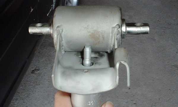
The
final steps in the fabrication of the perches includes the bending
of
the middle section of the journal so that the studs protruding from the
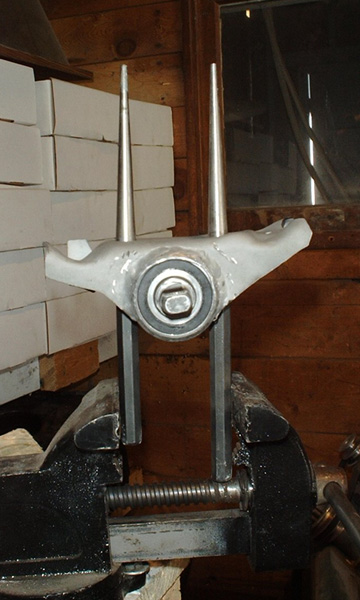
end of the shock will clear it. This is accomplished by
placing
two
pry bars or punches in the shock mounting holes of the perch
and
then use
a
bench vice to squeeze the two shafts together and, thus, bend the
journal. As you apply pressure with the bench vice, it is a
good
idea
to turn the shaft of the perch to make sure that the pressure from
bending the middle of the journal is not binding up the bearings.
CAUTION make sure that the dent is deep enough on both sides of the
perch so that
you can get a socket on the nut. I made the mistake of having
one
perch not dented enough and it took me over 2 hours to remove the
spring
compressor and install the shock on that side.
All
that is left now is to press the mounting studs back in the center
section of the perch. This is accomplished the same as
removal
with a
press, or hammer and the 1” long piece of
3⁄4” square
tubing. If you
are reusing the original studs, make sure they are examined for damage
and deemed reusable prior to instillation. One trick in installing the
studs that might be considered is to press the bolts in, in the
opposite direction from which they came out, that way the stud is
creating new groves in the mounting hole rather than seating the stud
in the old groves. The perch is now ready for
painting and
instillation. There you have it, the step-by-step process for
fabrication of a roller spring perch.
Rebuild Kit
R14-RS bearings.
Stud being hammered out
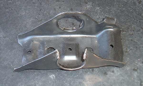
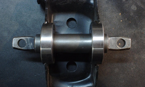
Perch after the center shaft is removed
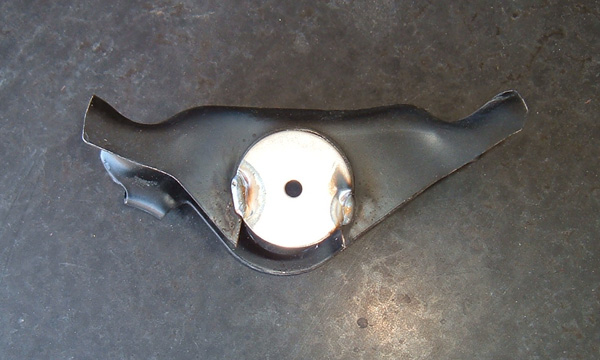
Washer welded in to serve as a pilot hole
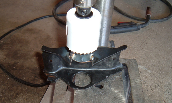
Drill press used to cut 2" hole in perch
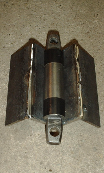
Not much left of the original perch
Bearings can be slid on the shaft for test fitting and measurements
This jig is vey simple to make and makes holding round objects easy
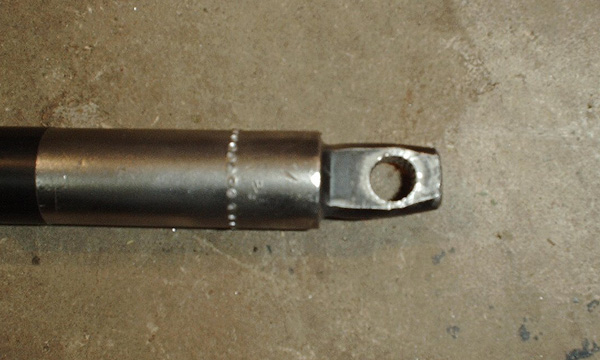
Once the tape is peeled off the shaft is left with a nice straight line
of divots for the bearings to seat against
The bearings and shaft resting on the 7/8" socket so that the bearing
can be pressed on. If you look in the picture you can see
that
more than half of the width of the divots have been covered by the
bearing
The
journal
has been cut, filed, squared and honed so that it can be installed in
the perch
It is important to hold the journal in place without bending
it.
A small piece of angle iron with the center corner ground flat is
perfect for clamping the pipe to the perch.
The journal needs to be ground smooth after welding, and then. with the
aid of the brake hone, the surface can be prepared for easy
instillation
of the bearings.
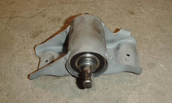
With the bearing shaft assembly slid in, the leading edge still needs
to
be tapered in to hold the assembly in place
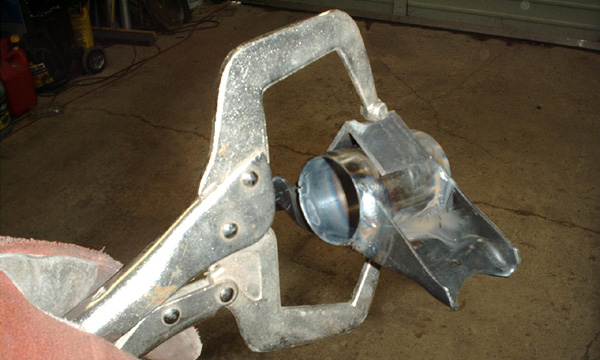
The width of the journal is too wide for the shock studs to fit past
it, but only just barely.
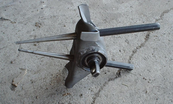
Two long punches can be fit through the holes and used to bend the
journal so that the shock bolts will clear.
A
bench
vise provides consistent even pressure to produce two dents with
uniform depth, length, and shape.
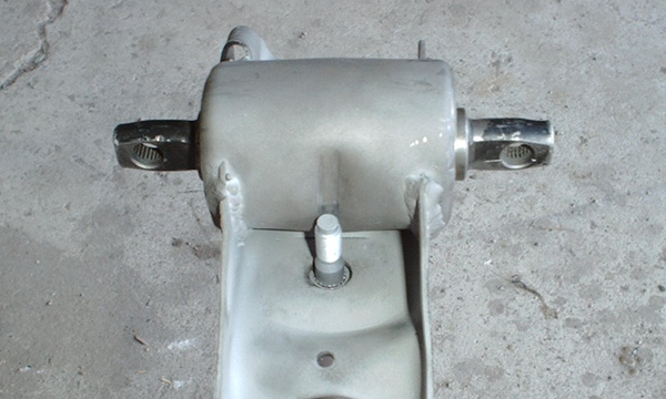
The dents now provide plenty of room for the shafts to slide past the
journal.
Other
Things To
Consider:
There
have been some concerns expressed as to the reliability
of
using a
ball bearing in this application, due to the immense pressure placed on
the perch by the spring, and the simple fact that ball bearings are
designed to handle pressure on a rotating load. This is a
valid
point
and warrants routine checks of the perch on a mildly regular basis to
ensure that it is still functioning the way it was intended
to.
This
routine preventative maintenance should not need to be carried out any
more
regularly than the checks normally made on ball joints, tie-rod ends,
or control arms. The static load capability of the bearing
used
should
be adequate, especially considering the following info:
There
are two ways to approach
this, first of all with
a spring rate of 600lbs, it takes 600lbs of pressure on the spring to
compress it 1 inch. The compression ratio should be a smooth
curve
sloping up so, in theory, each 1 inch compressed should require the sum
of the first compression weight and the last compression rate, which
should be greater than the rate preceding it.
Example: if
600lbs gets
you 1 inch, 1200lbs might get you 1" + 7/8", and 1800lbs might get you
1
" + 7/8" + 1/2" (these numbers are just an educated
guess).
To put it
another way, it may take 600lbs to go 1-inch, 1400lbs to go two inches,
and 2400lbs to go 3 inches. With all that said, a new spring
probably
doesn't compress more than 2" during normal driving. That
would
make
the static load between 1200-1800lbs. Because these numbers
are
educated guesses, I will go with the higher number of
1800lbs.
The
typical r14-rs bearings will handle a static load between 1100 and 1500
pounds. There are two bearings in each perch, which each take half of
the compression
load, effectively cutting the pressure in half. So each
bearing
is
capable of handling 1100lbs and only receiving 900 during brief extreme
situations. Also, during extreme compression, the bearing is
moving
more
and achieving some turning radius, thus transferring pressure to
several balls in the bearings. Lastly, due to the continuous pressure
from the spring and the give that the spring provides, there would
never be any jarring or impact force applied to the bearing.
That
is
unless the wheel left the ground for a long enough time to allow the
A-arm to travel to its most extended point and then come back to the
ground with enough force to compress the spring, and at that point, you
probably have bigger problems than the strength of a bearing to deal
with :) The other way to look at it is this, if the
car
weighs 3000 pounds 60% of the weight is on the front wheels;
in
this case 1800 pounds. That weight is divided among two
perches
and thus 4 bearings, this means that each bearing is supporting a
weight of 450 pounds, which is only 41% of max static load capacity.
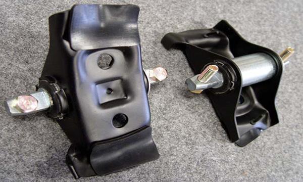
Roller
Spring Perchs
Made by Opentracker and sold DazeCars:
Looking
for completed spring perches ready to install? I sell high quality
roller spring perches ready to
install. Go to my For
Sale Page
for pricing and ordering information
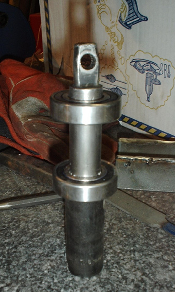
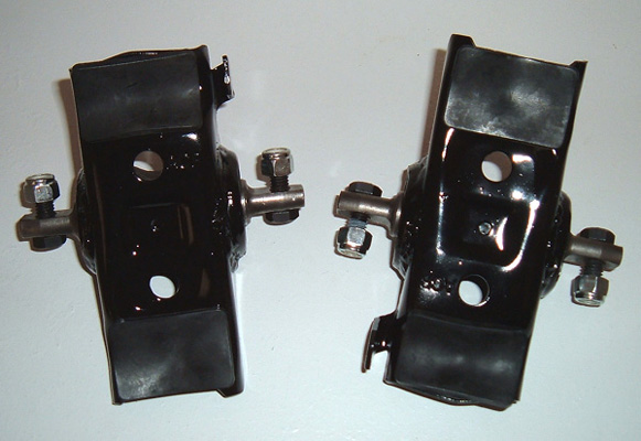
Opentracker perches
Here we have it a
completed pair of roller spring perches ready for
instillation.
Disclaimer on Daze Tech Tips
I am not an expert
in this field. I have performed these modifications myself with very
good results. I am passing along restoration and
performance tips for the purpose of education. If you are
concerned about reliability or safety issues, I do not recommend that
you or any other individual perform these changes or attempt to modify
your cars from stock configuration except under your own
volition. I do not assume nor accept any liability for the
use of
this
information or how it is applied.