 |

Argument
for setting up a
matching pinion angle and transmission angle:
The following info was posted on the NSRA forum: First
and foremost a universal joint is NOT a constant velocity joint. (This
is where the concern lies) This means if iu-joint is on a shaft at any
angle other than zero, the u-joint is NOT rotating at a constant
velocity. It is
actually constantly accelerating and decelerating on each revolution as
the joint is working itself around the angles. At one point it
has
further to travel because of the angle and so speeds up and at another
point it has less distance to travel and so slows down (relative to the
transmission speed). This means the drive shaft is rotating in a
'jerky
'movement constantly slowing down and speeding up. Now down at
the diff end this "jerky" rotation
will be transferred to the diff u-joint which will be transferred to
the wheels so what we would have is the trans trying to drive the
wheels at a smooth constant speed but the u joint is trying to slow
down and speed up the wheels. This means they are in conflict together
causing stress and vibration. The more the angle the worse this
'jerky
movement becomes. Now to get over this if the diff pinion is set
parallel with the transmission output shaft the u-joint at the
differential is also rotating with this 'jerky'
movement, slowing down and speeding up each revolution but its equal
and opposite to the transmission u-joint so they cancel each other out
and the
result is the diff pinion and trans are rotating together at constant
speed however the drive shaft is still slowing down and speeding up.
Twice per rev in fact .if the diff pinion is not set parallel with the
trans then this canceling effect does not take place and so the
differential
will not be rotating at a constant speed in relation to the trans.
34chip This info is WHY we need to set up the correct pinion angle in any car, but when you point this out to half the individuals who have put an IRS in their car, truck, or hot rod you get one or all of the following replies, with the first one being the most common: "It
doesn't apply because the
Jaguar differential is hard mounted where as a live axle differential
moves up and down with suspension travel"
In my opinion this first response is nothing more than something that "sounds good" to try and justify doing it, but really has no bearing on the issue. As the pinion on a live axle moves up and down the angle (in theory) is not changing and the pinion is remaining parallel to the transmission, further more if the road is smooth and the live axle springs are stiff enough the amount of differential movement will be minimal, and you still need the correct pinion angle to prolong u-joint life. "Jaguar
didn't do it that way"
This second response, I believe, is the main reason this debate has two divided camps. “Jaguar did it that way so it must be correct.” To a point I tend to agree with this sort of thinking. Personally having no formal training in engineering I must trust the designs of those that do, however this argument is in my opinion only completely valid IF AND ONLY IF you set the system up completely as Jaguar designed it, with a cage, with Jaguar cage mounts that have a specific amount of flex designed in to them, with Jaguar trailing arms, and with the transmission angle at 3 degrees down. The more of these things you change, the argument “that’s the way Jaguar did it” becomes less and less valid as you are not setting it up the way Jaguar did. "The
lower control arms (wishbones) on a Jaguar XJ6 IRS are perpendicular to the
pinion flange so mounting the diff at 0 degrees pinion angle allows the
suspension to move perpendicular to the road. If you set the pinion at
an angle the wishbones will also be at an angle and move backwards as
the suspension compresses.”
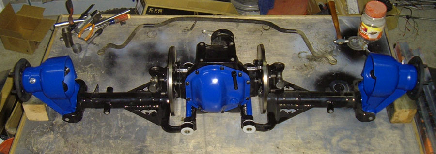
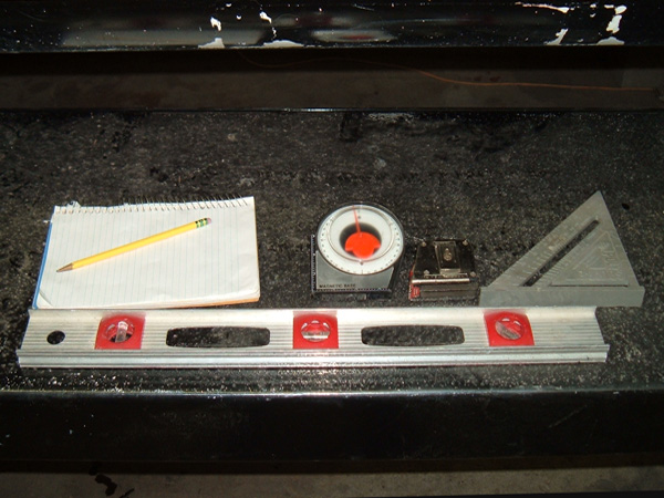
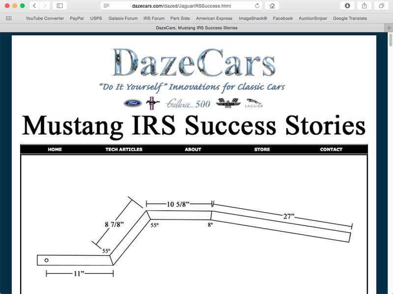
This third argument IMHO has the most validity, and I speculate is the reason that Jaguar did things the way they did. If the pinion is perpendicular to the ground the wheels will stay centered in the wheel well, and all forces will be applied vertically. All that said I do not see, with only being 5 degrees off of perpendicular, that there would be that big of an issue. I did a little math and with a 5-degree angle on the wishbones 3” of suspension travel would only result in .262” of backward movement at the wheel. A leaf spring set up moves the wheel backwards at least that much as the spring compresses so I fail to see the issue. With all this in mind I my priority was to match the pinion angle to the angle of the transmission. I felt that u-joint life and a reduction in vibration was more important than the wishbones moving perfectly vertical to the road. Taking measurements and Leveling the Car: With the issue of pinion angle sorted out (or so I though, this comes up again on page VII) we can finaly get some actual work done. Prior to removing the old system, it is a really good idea to take measurements of how all the OEM suspension parts are positioned. Also taking many digital photos is an added point of reference, should you find you need them during the IRS install. This will give you a relatively good idea of where the IRS components need to be placed in relationship to the rest of the car based on the location of the original suspension. A tape measure, level, angle finder, and note pad and pencil will be needed to take and then record all the measurements. The basic measurements like distance from the top of the differential to the underside of the car, distance from the axle tubes to the under side of the car, wheels in relationship to the fenders, axle tube in relation to the front leaf spring bolts and any other dimensional measurements can be taken using a tape measure. NOTE make sure all measurements are taken based on a fixed location in the car that will remain intact after the rear suspension has been removed.
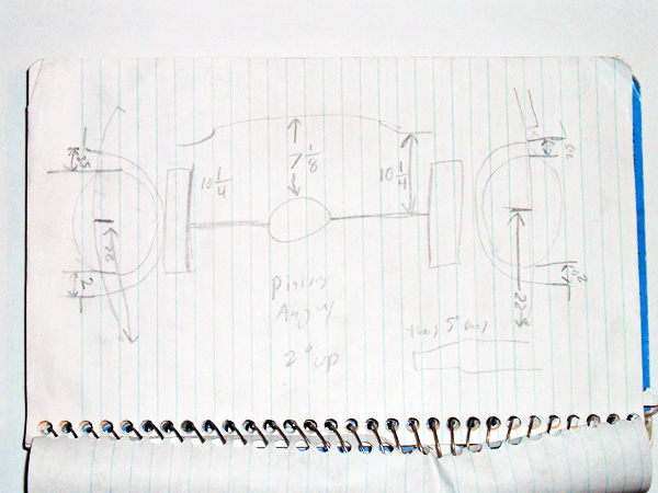
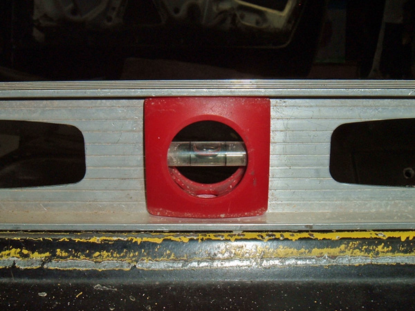
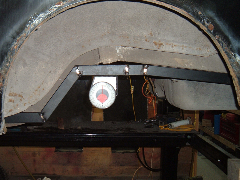
To accurately record all these measurements it is a good idea to draw out a picture and then write down all these measurements on said picture. You may find that there is a slight variation from one side of the car to the other, and if this is the case determine if it is a result of the components being misaligned or if it is something on the actual car that would need to be addressed prior to the install of the IRS unit, such as a bent frame rail. In order to accurately take measurement of things like pinion angle and transmission angle, it is a really good idea to level up the car. This step is not totally necessary as you can figure out pinion angle by measuring said angle and then measuring the angle of the cars stance than using the two angles to do a simple calculation, however, by leveling up the car you eliminate the need for calculations. With the car level, you can simply measure at the pinion or transmission. This is not only important during the initial measuring but will also need to be kept in mind once the actual install begins. Having a level car as you fabricate pieces will make it easier to get said pieces correctly positioned. Prior to being able to level your car you must find a place on the car that would be level if the ride height was the same at both the front and rear wheels. On a mustang the rocker panel offers several locations that this criteria applies to: the pinch welds just under the rocker panel, the flat area next to the pinch welds on the underside of the rocker panel as well as the top of the rocker panel when the door is open and the scuff plate is removed. Keep in mind that any surface imperfections can make all of these places less accurate. There may be adhesive on the top of the rocker panel where the scuff plate was, or the spot welds on the pinch weld may make the lower edge uneven.
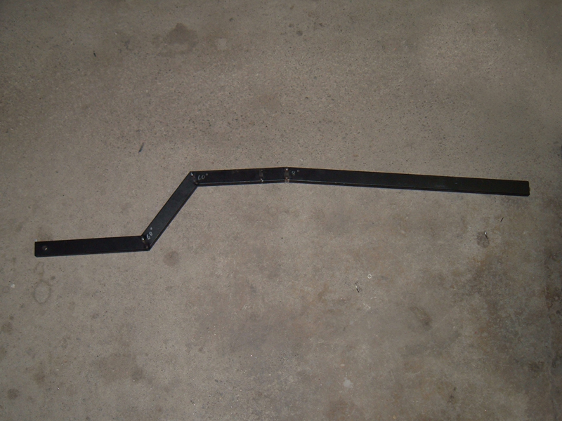
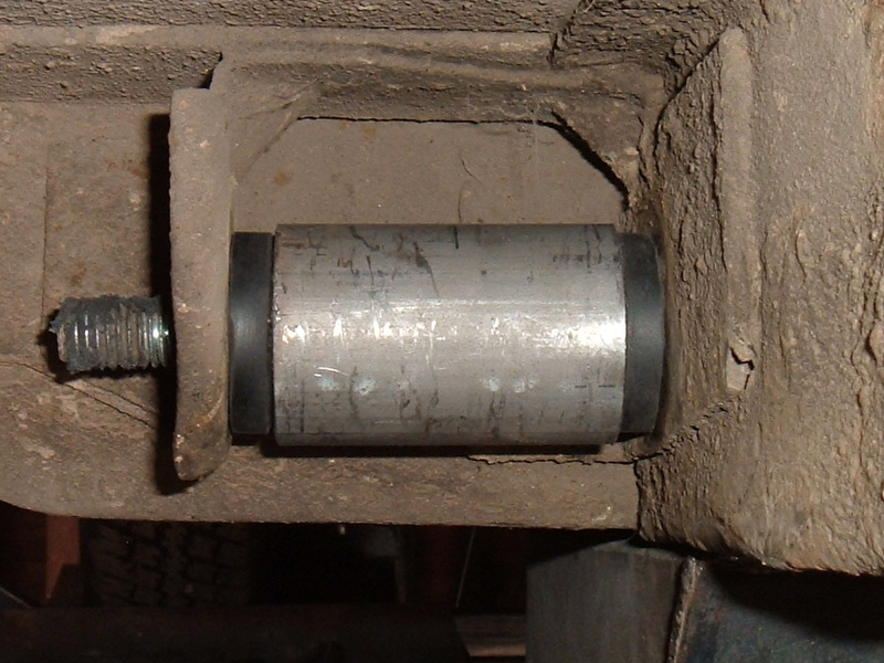
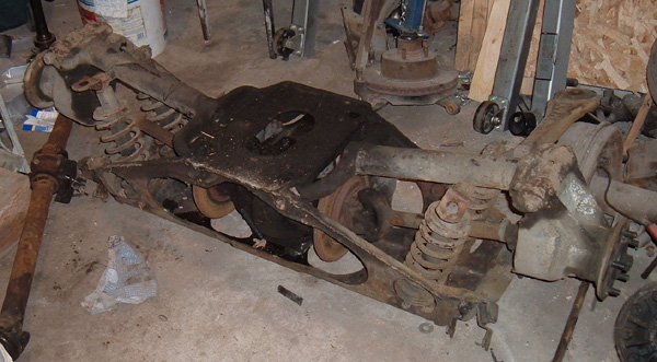
Keep such imperfections in mind and eliminate theses issues as best as possible. A good example would be to scrape the adhesive off of the rocker panel. Another way to help eliminate issues caused by imperfections in the rocker panel is take lots of measurements from lots of different areas, using several different measuring tools. The more information you collect the better opportunity you have to make sure you have the car as close to level as possible. I used several levels and my angle finder to get my car correctly orientated. After each measurement, to actually adjust the cars stance and level it up I simply let a little air out of the tires, took more measurements and then repeated the process until I had the car level. NOTE Keep in mind the car needs to be level in all directions, not just front to back. Once I had the car level I was able to use the angle finder to check pinion angle at the differential and more importantly the angle of the transmission. As talked about in great detail above, the transmission angle is critically important to achieve the correct pinion angle on the IRS unit for the purpose of insuring long u-joint life. In order to measure my transmission angle I used an old slip yoke that had an inner surface that was perpendicular to the mane shaft of the yoke. To get it truly perpendicular I had to lightly run a file over the surface to remove a bur. With the yoke in place I was able to take the measurement and found that the T5 transmission in my car hangs down at an angle of five 5º. Removing the OEM parts : There is not a lot of technical skill needed to remove the OEM parts. There are however a few things to keep in mind prior to the removal of the parts. First penetrating oil is your friend!!! Several days before I removed the rear end, shocks, and leaf springs from my car, I applied liberal amounts of penetrating oil to all the bolts and nuts that would need to be removed. This step was done many times and made the removal easier, but I still had some difficulty removing the nuts from the u-bolts on the underside of the leaf springs. The other thing to consider is make sure the car is solidly supported so that the rear end parts can be safely removed. To accomplish this I placed jack stands under the rear pinch weld at the jacking notch as well as a cross support under my sub frame connectors. Supporting the car at just the pinch weld or at just the sub frame connectors probably would have worked, but there is no reason to support the car in just one location if you can support it in several. This will add extra stability, and in turn make working under the car safer. With these things in mind I was able to easily get all the old parts out and take a good hard look at what I would need to fabricate to install this unit. My plan has always been to make this install a complete bolt in and with all the original parts out of the car I was able to confirm that this plan will be easily attainable. Why make it a bolt in? It has been said that it might be a lot easier to cut and weld the underside of my car to accommodate the IRS unit rather than trying to make this a bolt in so why go through the trouble? There are lots of reasons. Will I ever remove this set up and go back to OEM equipment?? Probably not, than why make it a bolt on?? Well there are 4 reasons: 1. Some day the car will no longer be mine. Hopefully that won't be for another 50-70 years, but the reality is some day I will be dead and gone and the car will hopefully belong to my daughter or one of her kids. With that in mind, even though I love to modify things I try to make all my modifications easily undoable. This way if I change my mind in the future or some future owner wants to do something different they easily can. 2. Ford did it that way. The IRS Ford designed for the Mustang was built with the idea of it being a dealer added bolt on and even though my install will not be exactly the same, in many ways I am trying to emulate that original design 3. STRENGTH. The rear frame rails on a Mustang are way to thin IMHO. If I weld mounting brackets on to the frame that would put a lot of stress on the middle section of the frame, and more specifically on the thin frame walls. I know the weight of the, back half of the car can easily be supported by the leaf spring mounting locations so I want my set up to attach there 4. Making it a bolt in gives me the opportunity to use mounting bushings. As you know Jaguar put all the parts in a self contained cage and then used rubber bushings to mount said cage to the car. By using the stock leaf spring mounting locations I can easily use leaf spring bushings to accomplish the same thing. Leaf spring bushings are durable, easy to find, availably in several different materials depending on desired stiffness, and will work well in isolating the mounting frame from the chassis. NOTE prior to beginning the fabrication phase of the install make sure the car is still level. Changes in the weight of the rear half of the car may cause the front suspension to shift and the car may need to be re-leveled. In fact it is a really good idea to make sure the car is still level at the beginning of each and every work session. Building a pattern for the side rails: To make it a bolt in I had to come up with a suport structure to that utilized the factory leaf springs and run along the curves of the original frame rails. Rather than start with the actual material I will be using for the supports, I decided to make a pattern using some .75" X 1.5" tubing with 18 gage walls as it was scrap I had laying around, was easy to work with and was light. As I started to build the pattern, I relied on my tape measure, and trial and error to come up with the correct angles. After about an hour I realized that I could easily get the angles I needed by using my angle finder in the mustangs frame rails. With an accurate way to measure the frame the piece came together quickly. 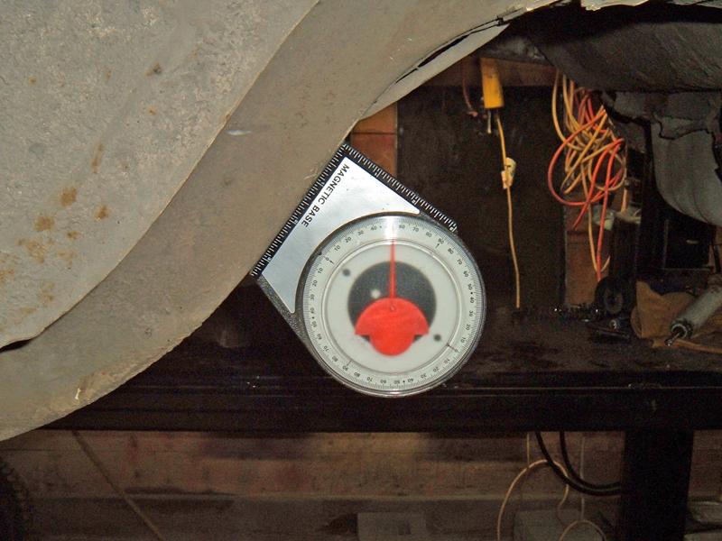 As you can see it fits well and the design provides a nice level center section to weld in tubes that will connect the two brackets together. From there I can hang the Jaguar parts from the cross tubes.
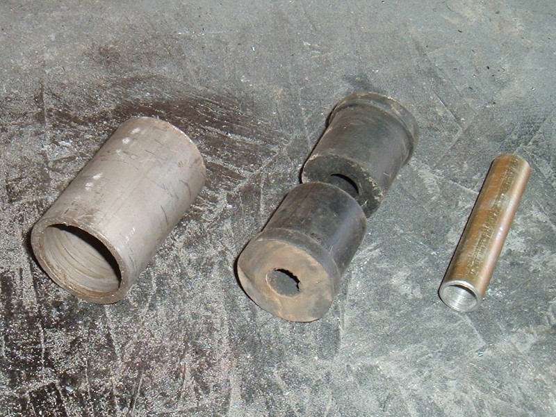
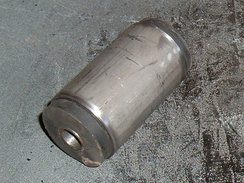
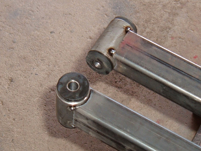
The pattern will be used to make the final units out of 1.5" X 2" rectangular tubing with .120 walls. As I was building the pattern I was trying to decide weather to notch the tubing, bend it, then weld it back together my self, or have it bent, at a local shop. Even though the bent tube would probably be cleaner I decided I want to keep this a DIY as possible so I will use the notch and weld method, besides then it will match my sub frame connectors. Building the bushings for the OEM leaf spring mounts: The front mount is a custom bushings and has a sleeve that will be welded to the front of my side side rails and bolt up in the leaf spring mounts. To build the bushings I started with Mustang shackle bushings and some 1 & 5/8" mechanical tubing. I used my bench grinder to grind the domes off of the shackle bushings. I machined the outer sleeve and inner sleeve to be a tight fit in the spring mount. The hole in the shackle bushings is 9/16" and the inner tube is 5/8" so by pressing the inner tube in to the bushing it expands making it a tight fit in the outer sleeve. I am really pleased with the final install. They fit tight and once the tubes are welded to the end of the side bracket I will have a solid front mount.
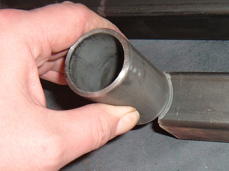
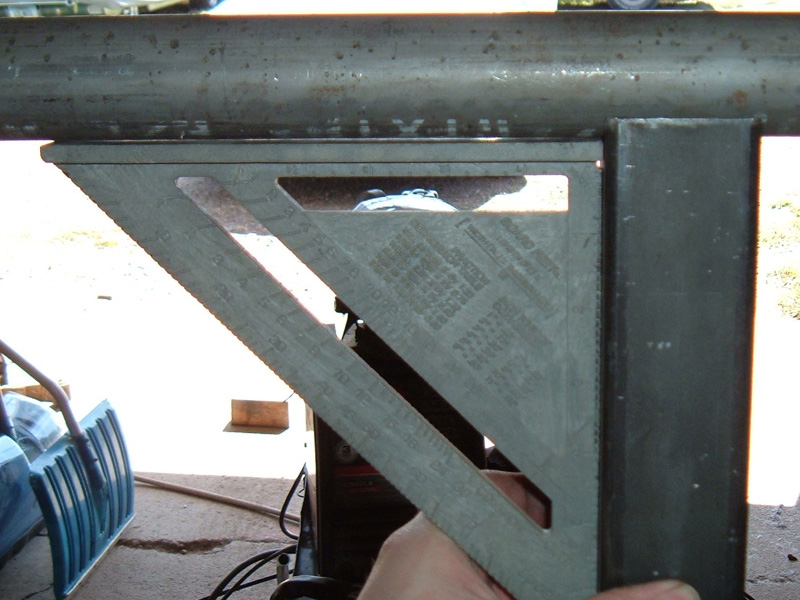
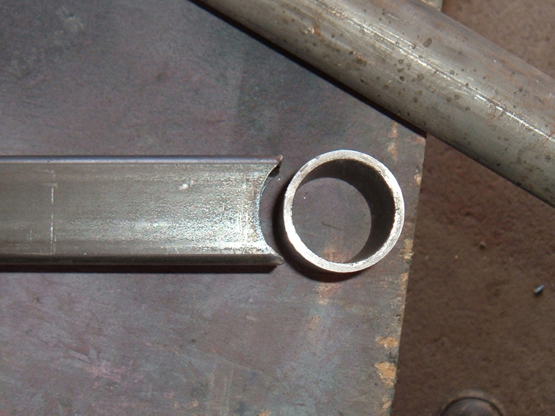
Making the notch was easy enough I used the sleeve to mark the notch and then ground out the material. From there I took a long piece of the same tubing I used for sleeve and placed it in the notch. This gave me something to put a square up against to make sure that my notch was true.
In fabricating my side rails, I started with the mount end because this end had the most chance of being different, one rail compared to the other. The reason for this is if I started with shaping the rails and then installed the sleeve, if one notch is deeper than the other than it would change the length of rail. However, by starting with this end, if one notch is a little different than the other it doesn't mater because I now can measure from the inner sleeve bushing and make sure both rails are identical. As we go on to Page VI we will look at the process and problem solving that was required to build the subframe.
|