Building adjustable strut rods for your early Mustang is easier than you might think
"The step by step process of fabricating heim type adjustable strut rods for an early classic Mustang"
Benefit of adjustable strut rods
Through
the course of my restoration project, I have done extensive research
into Mustang suspension and ways to improve it. Through this
research, I have learned that adjustable strut rods are an obvious
choice as a means to improve suspension and handling. To understand why
they are so effective, you must first comprehend the function of the
strut rod in a classic Mustang. The strut rod is there to
stabilize the lower control arm in a fixed position that prevents
its movement forward and aft, but still alows it to travel vertically
with suspension compression and decompression. The stock system is
designed so that, during regular driving, the rubber bushing gives,
allowing vertical travel as the lower control arm moves up and
down.
The give in the bushings, unfortunately, has a negative
side effect of unwanted movement, they compress and stretch during
braking and acceleration. The result of the compression and stretching
of the rubber bushings is an increase and decrease in the length of the
strut rod. As the strut rod increases and decreases in length, the
lower control arm is not held fixed and can move forward and aft a
small amount, which puts the alignment in a constant state of change
during driving. One option to remove the compression and stretching of
the stock rubber bushings is to replace them with polyurethane
bushings. The polyurethane reduces the movement of the strut rod, which eleviates the issue of compression and stretching, however,
it has the unfortunate consequence in that it increases the effort
required for normal strut rod movement during suspension travel
and puts far more train on the strut rod than it was ever designed to
handle.
I have seen many times where people have bent or broken
their stock strut rods by replacing the rubber bushings with
polyurethane.
With negative
side effects from both rubber and polyurethane, the challenge is to
have a joint that freely moves vertically so as to not overtask and
damage the strut rod, but is also fixed in such a way that it cannot
shift forward or aft. This can be easily accomplished by using a heim
joint at the bushing end of the strut rod. An added benefit of a
heim joint system is that by having two threaded ends with opposite
thread directions, one on the heim joint and one at the base of the
strut rod, you can use a threaded connecting tube and make the strut
rods adjustable for an easier and more fine tuned alignment.
10/09/12
The original web site I created describing in detail how to make these
adjustable strut rods used a cast steel part at the frame.
However the company that sold the cast steel parts has switched to a
cast iron part which I do not feel is up to the task of strut
rods. I am working on making another part work and will repost
the info on this page once I have updated it. consiquently I do
not recomend using the cast clevice.
Adjustable strut rods are such a popular and effective way to
improve Mustang suspension and handling that there are many aftermarket
performance part manufactures producing them and they are selling
for prices of $300.00 a pair or more. I found this cost to
be quite high, especially when very few fabrication skills and tools
are required to make a set at home. The following is the process
I used to build a set of adjustable strut rods for my 1964 & 1/2
Ford Mustang. The process will work for later year Mustangs, as
well as Falcons and Cougars but measurements will be required to
account for changes made in various models and years, but the
process and basic concept is the same for all vehicles utilizing this
style of strut rod in the suspension.
At first, building a set of adjustable strut rods at home seemed
relatively straight forward. The only obstical that needed to be
overcome in building them was the frame mounting point. In
the aftermarket and in home garages, there have been many solutions to
the mounting issue, These solutions have included drilling mounting
holes through the side walls of the frame and running a bolt directly
through it with spacer sleeves on either side of the heim to center
it, fabricating a welded together bracket that mounts to the
original bushing holes and attaches to the heim, and milling out or
casting a solid one piece unit. These are all fine options with
their own pros and cons. I, personally, am not fond of the idea
of drilling holes through the supporting rails. The main issue I
see with this option is that it would be very difficult to get a good
straight hole drilled through the rail while it is still under the
car. For me, the welded bracket seemed like a much better way to
go, but I had reservations doing the welding myself, being that I
wanted to make sure that the piece would handle the stress that
would be placed upon it. All these factors forced me to put my
adjustable strut rod project on hold, with the intent to eventually
have a set of brackets fabricated at a local machine shop. The
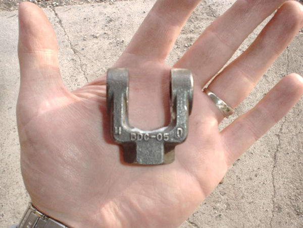
project was revived when I was informed of a company that had a
clevis that would be perfect for my application. This company
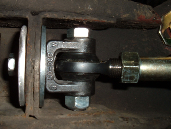
sold a cast steel threaded rod clevis that has a load capicity of 4250
LBS. (part # RC-05) Its dimentions are such that once a bolt has been
run through it and a nut placed on the bolt and torqued down, the
assembly fits perfectly up between the rails at the strut rod mounting
point. The distance between the eyes on this clevis is 3/4",
which is perfect for a 5/8" heim joint by itself and, with a little
modification ,the opening can be widened to accomodate the heim with
two rod end seals, one on each side. Finding this piece gave me
everything I needed to finish the project. The following is the
process I used to fabricate adjustable strut rods at home. NOTE:
12/12/11 I recently received an email from some one who had one of
these rod ends shear. It was most likely a bad casting but just
something I figured I would pass on. The strut rods on my car have been
there for over 7 years with out issue. The other issue that has
arisen is some suppliers litst this part as cast steel while others
list it as cast iron. They all look the same and have the same
casting #s so I would assume they are the same and probably cast steel
due to the strength specs BUT there is a big difference between cast
iron and cast steel and I will be looking for somthing stronger.
UPDATE:
07/07/19 After much searching I found a fordged steel component used in
steering that could be used in place of the cast rod end. There
is info on this and how I fit it to myu car at the bottom of the
page. The rest of this page up to that point deels with the cast
rod end and the modification of the OEM strut rod. Using the
steel celvis was a direct swap for the cast rod end and all the other
info on this page applies.
Tools required for the project:
Metal cutting saw, grinder, die grinder with cut off wheel and small
conical grinding stone, angle grinder, calipers, 5/8" fine thread die,
flat file, and a rat tail file.
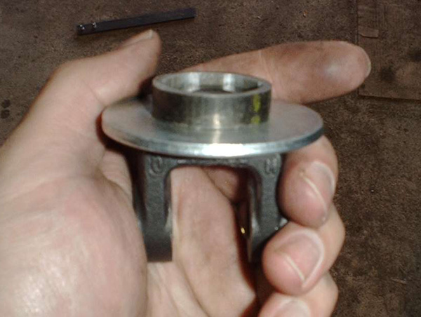
Threaded rod clevis, the part that makes it all possible.
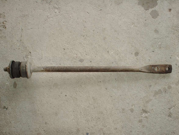
Stock strut rod with rubber bushings on one end.
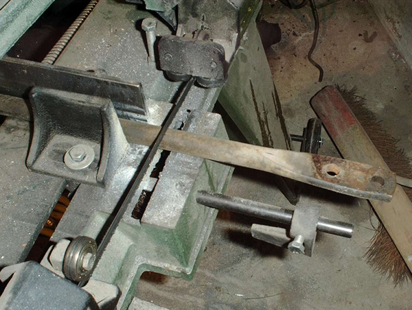
Stock strut rod being cut at 8.5" so that it can be thread
Process:
The first step is to begin by modifing the stock strut rods. As
with any modification to a stock used part, it is extremely important
that you are beginning with a sound componant with no obvious wear or
major defect. In the case of strut rods, you want to look for
extreme bending or cracks. Once you have determined that your
strut rods are a solid platform from which to build a modified part,
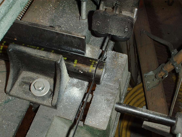
you can begin by cutting them. In the case of my application, I
cut them to a length of 8.5”, measured from the lower control arm
end. I recommend taking your own measurements and determining
where you want to cut the strut rod, based on the length of the swegded
tube you chose to use. I am running an aftermarket 1” sway bar and was
concerned about clearance issues, so I chose to use a 10” swegded tube
so as to maximize clearance and locate my jam nuts as far away from the
sway bar as possible. After the strut rod has been shortened,
about 2 & 1/2" of the rod needs to be turned down to 5/8” and
threaded. The reason that the strut rod is not left at the 3⁄4”
thickness and simply threaded at that size is that, by doing so, there
becomes clearance issues with the larger 3/4" swegded tube and
corresponding larger heim joint. There is no real concern about
removing metal from the strut rod. The heim joint frees up the
strut rod's movement and reduces pressure on the rod. 5/8”
is large enough considering the new freedom of motion. There are two
ways to get the strut rod to the required 5/8” size. The first is
to use a lathe. If you have your own or access to one, you can
turn it down to the correct size. If you do not have access to a
lathe, you can take it to a local machine shop and have them turn it
down and thread it for you. Option two, and what I did, is to use
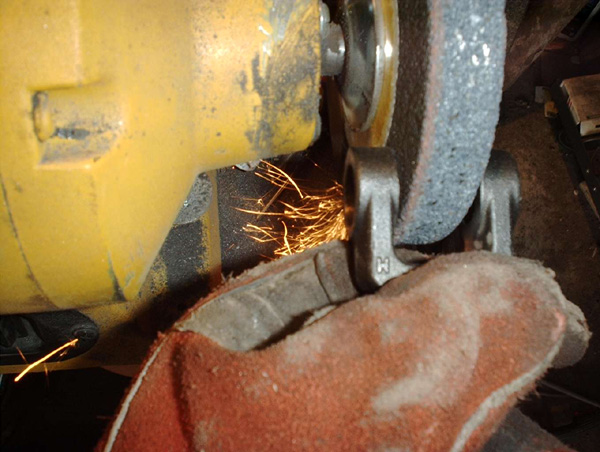
an angle grinder and cut an octagon shape into the rod. This is a
tedious process that takes lots of double-checking and patience, but is
very effective and only costs your time. Start by placing the
strut rod on the floor or bench with one of the flat sides down.
Hold the rod firmly against the floor or bench and use an angle grinder
to flatten the up side until the flat stripe measures 3/8” wide.
You then flip the strut rod over and do the same thing on the other
side. Once both sides have been cut, take a thickness measurement
between the two flat sides. If the thickness is greater than
5/8”, continue taking a small amount of metal from both sides until the
thickness is slightly greater than 5/8”. You can then turn the
strut rod on its side and repeat the earlier steps so that you are left
with a 5/8” square rod. The same technique is then used to cut
the 4 corners of the rod, so that you now have a 5/8” thick piece of
octagon rod. A flap disc can then be used on the angle grinder to
round off the 8 corners of the octagon to convert it to a round 5/8”
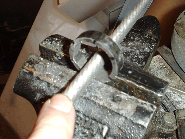
rod. The strut rod is now cut to size and can be threaded to 5/8"
fine thread. CAUTION;
as you are grinding do not let the rod overheat!! You want to retain
its original temper. Also, it is very important to take small
amounts of metal off at a time and measure often so that you do not
remove too much metal. I cut mine down to .65” and used the
threading die to remove the remaining width as it cut in the
threads. When cutting threads it is important to use a quality
die, lots of cutting oil, and to take about 1/16 of a turn forward and
then a half turn backward to constantly clean the new threads. If
you do not take small bites and constant back turns, you will break the
tips of the threads off as you are making them. Now that the
strut rod has been sufficiently modified, we can turn our attention to
the other end of the assembly and modify the heim joint.
Please note: not all heim joints are created equally,
some are of high quality and some are not. Strut rods absorb lots
of stress and strain, so this is not a place to cut corners and go with
a poor quality part just to save a few bucks. A heim joint can be
purchased with a 5/8” shank and a 1/2” hole, however, it is cheaper and
just as effective to buy a 5/8” 5/8” heim and press a 1/2” I.D. and
5/8” O.D. bronze bushing into the heim’s eye. In the case of my
strut rods, I chose to use rod end seals on either side of the heim to
keep out contaminates and, thus, prolong the life of the joint.
The seals add .05” to each side of the heim, making it .1”
thicker. With this in mind, I wanted the bronze bushing to
protrude out of the heim a small amount on both sides to hold the seals
in place. It is important that the bronze bushing does not
protrude past the rod end seals so I measured the thickness of my heim
.75” and added .075” to account for most, but not all of the rod end
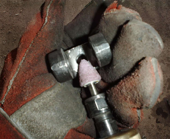
seals thicknesses. Using a cut off wheel, I cut the bronze bushing
to .825”. I then used a file and cleaned up the end I had
just cut. The bushing is now ready to be pressed into the heim. I
did this in a vise. The process is relatively straight
forward. Simply start the bushing in the heim, place them both in
the vise, and close the vise to press the bushing in. It is
important that you make sure the bushing is seated squarely in the heim
before you begin to press it in. Also, once the bushing is most
of the way in, you will need to remove the heim from the vise and place
a washer with a 5/8” hole in it behind the heim and place them in the
vice to finish pressing the bushing in. This allows the bushing
to move slightly past the leading edge of the heim without bottoming
out in the jaws of the vise. The heim is now ready to be used on
the strut rods. Our attention can now be turned to the key component in
the homemade adjustable strut rod, and that is the threaded rod clevis.
The beauty of this part is that it is a solid one-piece unit, with a
4250 pound load capacity, and it takes very little modification for it
to be used in this application.
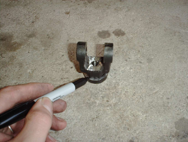
The first thing that needs to be addresed on the clevis is that the
opening between the eyes of the clevis is a perfect fit for the 5/8”
heim joint by itself, but will require enlarging to use rod end
seals. The advantage of using the seals is that the life of the
heim joint will be prolonged by protecting it from dirt, water and
other road contaminants. The disadvantage is that some of the
metal on the clevis needs to be removed to accommodate the .05”
thickness of a seal on both sides of the heim. This will require some
machining that will slightly weaken the clevis, but not significantly
enough to be of concern. I chose to use the rod end seals. In my
mind, the advantages far out weigh the disadvantages. Any machine
shop can mill the clevis opening to the correct size, however, as
before with the modification of the strut rod, there is a relatively
simple way to modify the clevis at home with a simple bench
grinder. There again, the only cost is time, but also, as before,
the process can be tedious and require repeated measurements to ensure
that the correct amount of metal is removed. To enlarge the
opening, simply slide the clevis over a grinding wheel and use the flat
side of the grinding stone to grind away metal on the inside of both
eyes. Frequently, remove the clevis from the grinder to
ensure that the surface is still square and to prevent the clevis from
overheating. The key to doing this accurately is to be patient
and take lots of measurements. Once the opening has been enlarged, our
attention can be turned to the clearance between the clevis and the
heim joint. Place the heim with a seal on each side in the clevis
and insert the 1/2” bolt. Most likely, the heim will bottom out
at the base of the clevis in the middle. A rat tail file or a die
grinder can be used to round out the inside of the clevis so that the
heim has 1/16” to 3/32” clearance between it and the clevis during its
full range of motion. It is important to have adequate clearance
so that the heim joint doesn’t bind up, but it is equally as important
to minimize the amount of metal that is removed from the clevis to
maintain the part's strength and integrity. Now that the clevis
has been fitted for the application, the aft retaining washer needs to
be modified to fit over the clevis, a spacer ring needs to be
fabricated to center the clevis in the mounting hole, and the forward
retaining washer needs to be aquired or fabricated.
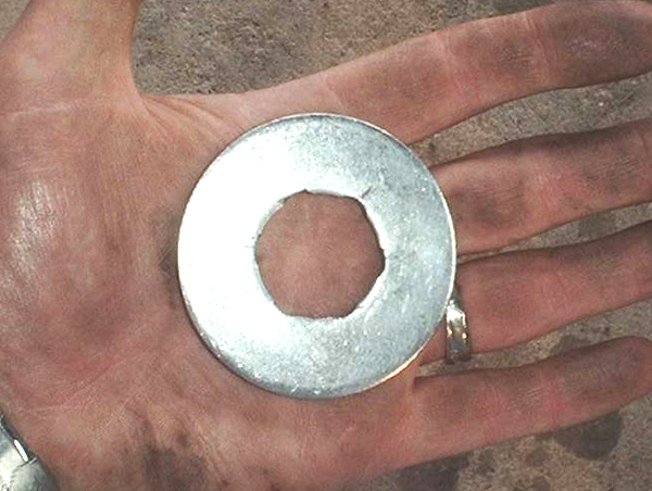
My local hardware store had oversized washers that measured a 2.5” O.D.
and a 1.125” I.D. I placed the base of the clevis over the washer
hole and marked each of the hexagon points. I then used a rat
tail file to remove a small amount of metal at all six marked
locations. This made it possible for the washer to fit easily
over the hexagon base of the clevis, and made a nice flat surface for
the mounting ring to rest against. I could not find a washer to
be used as the forward retaining point so I decided to fabricate
one. I took a piece of 3/32” plate steel and cut it into a 2.5”
by 2.5” square. I then used the straight edge from corner to
corner and an awl to scribe two perpendicular diagonal lines to mark
the center so that a 7/16” hole could be drilled out. Then, with
the aid of a cutting wheel and bench grinder, I transformed the square
into an “almost” round piece. To put finishing touches to the
washers, I bolted a 7/16” bolt through my newly fabricated washer,
mounted the bolt in my drill, and used the flap disc on my angle
grinder to round out the washer by lightly grinding it while I spun the
piece at a low speed in my drill. These processes left me with a
wonderful mounting surface that would press firmly against the mounting
plate and sandwich the required spacer ring.
When I was first contemplating how to best create a spacer ring, I took
careful measurements of the mounting hole in my Mustang, grabbed my
clevis and my calipers and headed to the hardware store. I was
pleasantly surprised to find that 1 & 1/4” steel pipe had a 1” I.D.
and an O.D. that was just slightly larger than 1.25”. These
dimensions made it a perfect fit for the mounting holes in my
Mustang. The next step was to determine the thickness of my
ring. I took many measurements of the mounting plate where the
strut rods pass through it and found the thickness of the metal there
varied in thickness from .368” to .372”. It is important that the ring
not be thicker than the mounting plate because, if the retaining washer
bottoms out on the ring, then there will be a gap between the washer
and the plate and this will cause play and movement in the mount.
It is equally important that the ring not be too small because without
metal on metal contact, many of the advantages of torking down the
mounting bolt are lost. Keeping this balance in mind, I decided
that my finished rings needed to be .365” thick. For me, it made
sense to error on the side of not thick enough and three to seven
one-thousands of an inch is a minimal amount of slack that will easily
be taken out simply by the retaining washers bending slightly during
torking. I cut two rings that were slightly thicker than .365" so that
I would have some metal to work with as I squared and cleaned-up their
cut surfaces . Even after the ends were clean and square, I left
them at a thickness slightly greater than .365”. I then used the
same technique as before with the washer and marked and filed the hex
pattern into the ring. With the ring, however, I removed small
amounts of metal and checked fitment often. My spacer rings are a
tight fit that need to be tapped on with a dead blow hammer or pressed
on by applying the forward retaining washer and tightening down the
retaining bolt. Once I pressed the ring on and tightened down the
bolt, I took measurements of the gap between the two washers on all
sides and removed metal on the ring in the places where the measurement
exceeded .365”. Many times, I removed the ring and made minor
adjustments by moving it across a file or 80 grit sand paper laid out
on a flat piece of metal. After each modification of the ring, I
reinstalled it on the clevis, tightened everything down and checked to
see what the measurement was between the two retaining washers.
The finished result was a solid front mounting point that is
equal in form and function to our modified strut rod end. There
are now only a few small details to address and the adjustable strut
rod project can be completed and ready for installation.
There is an issue you need to be aware of with buying a bolt that is
just long enough to fit through the clevis and have enough room for a
nut on the end, and that is that bolts of that length are threaded down
too far and some of the threads end up inside the heim and through one
of the clevis eyes. The problem with that is that the diameter of
the threaded part is just slightly less than 1/2” and that will create
some play in the mount. For best results, the 1/2” bolt that goes
through the clevis and the heim joint needs to be longer than required
and then cut to length. I found a bolt that the base of the
threads was about 1/4” inside the outer edge of the clevis eye, that
way, once the nut was torqued down, it would not bottom out at the base
of the threads. It is also important that the bolt be grade
5. Grade 8 is stronger but more brittle and I would rather have
the bolt that was going bend in extreme situations rather than
break. After taking careful measurements, I cut the bolt so that
when it was passed through the clevis it was one thread longer than
what was required to fit through the all metal locking nut. There
is very little clearance in the mounting rail so any extra threads,
other than one, will create clearance issues. The 7/16” clevis
mounting bolt will also need to be purchased long and cut to length.
For the same reasons as stated above, it also needs to be grade 5
rather than grade 8. It is important to have it long enough to utilize
all the threads in the clevis, however, due to a small amount of give
in the retaining washers, I recommend cutting the bolt 1/16” shorter
than is required to utilize all the threads, that way if when torqueing
there is give in the washers, the bolt doesn’t bottom out against the
heim. The last detail to address is that a spacer washer needs to
be placed inside the spacer ring between the clevis and the forward
retaining washer. I found that the clevis base was not quite long
enough the fill the spacer ring, and if you do not put a washer in to
fill that gap, you will warp the retaining washers when you torque down
the 7/16” bolt. As with the thickness of the spacer ring, it is
better to have a washer that is slightly thinner than what is required
to fill the gap rather than thicker. I was able to find a washer
that was the correct thickness and width to be a perfect fit.
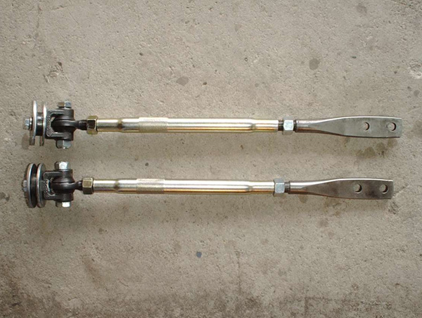
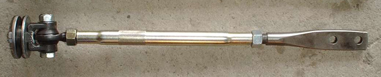
All the parts have now been fabricated and the only thing left to do is
assemble the strut rods and install them in the car. When putting
it all together, I recommend using lots of anti-seize oil on the heim
joint threads, strut rod threads, swegded tube threads and
corresponding jam nuts. I torqued down the 1/2” locking nuts onto
the 1/2” bolt that goes through the clevis and heim to 60 foot
pounds. The 7/16” mounting bolt was also torqued down to 60 foot
pounds and, when I installed it, I used lots of lock tite on its
threads to ensure that it would not come loose. There are
those of you who may be wondering why I did not do any welding to
attach the mounting washer and spacer ring to the clevis or to fill in
the gap between the clevis and the end of the spacer ring. The
answer is that a cast steel part like the clevis I used has lots of
internal tension that is formed during the casting process. When
you weld on a piece like that you mess with those tensions and
inevitably weaken the piece. Also, different steel alloys require
different types of welding rod so without knowing exactly what type of
steel the clevis is made of, you are far better off not welding on it.
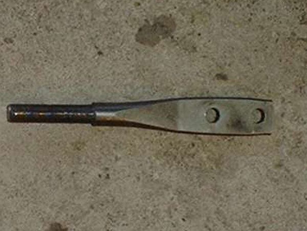
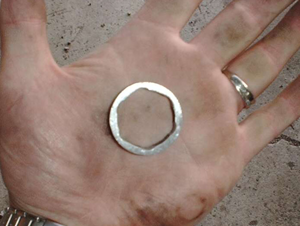
Cut, turned and threaded rod end.
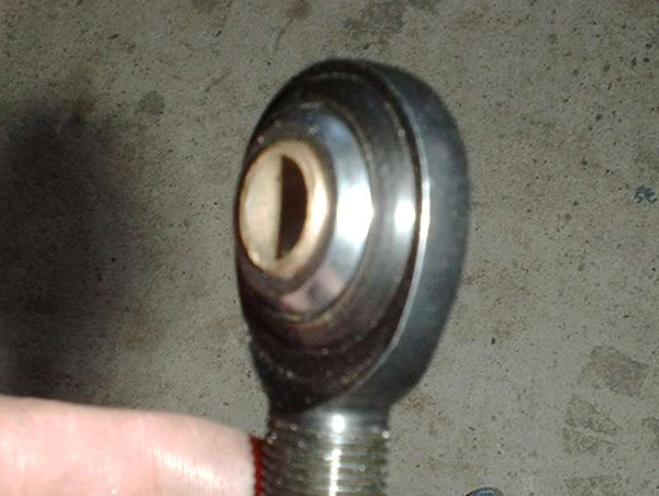
5/8" O.D. 1/2" I.D. bronze bushing being pressed
into a 5/8" heim joint.
Heim joint ready to install with a less than .05" lip of the bronze
bushing sticking through on either sides.
Inside edges of the clevis being ground down to make room for the rod end seals.
Base of clevis being ground to allow clearance between the heim and clevis.
The clearance is being checked and, as you can see, there is about
3/32" gap between the heim and clevis.
Spacer ring being cut from a 1 & 1/4" piece of steel pipe.
The hex points on the clevis need to be marked on the ring so that it can be shaped to fit.
A rat tail file works well to cut the hex shape into the ring.
As you can see, there is a clear hexagon pattern inside the ring.
The same hex pattern needs to be filed into the backing washer.
The washer is a perfect fit on the clevis.
My spacer rings are a tight fit over the clevis end. Notice the gap
that will need to be filled with a spacer washer between the end of the
clevis and the ring.
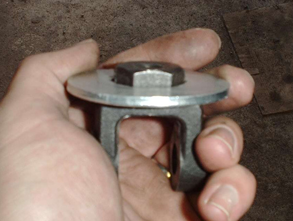
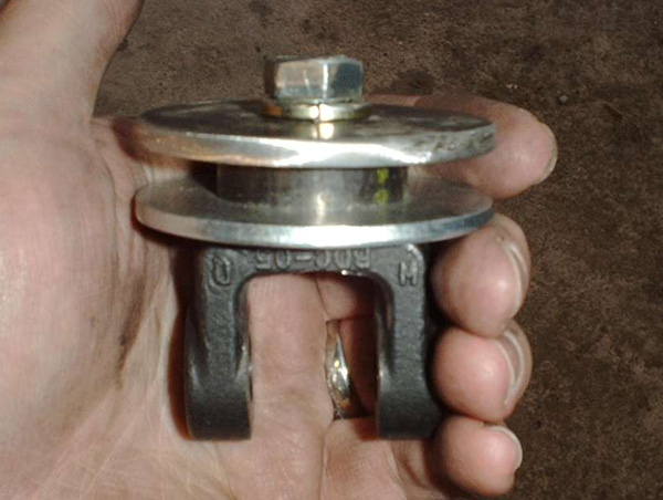
Complete frontal mounting assembly.
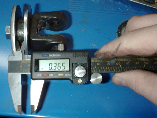
A gap needs to be established that is slightly less than the mounting
flange on your car. The spacer ring was machined to create a
.365" gap.
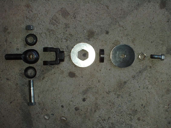
This is an exploded view of the mounting assembly. Not pictured
but very important is the spacer washer that goes inside the spacer
ring.
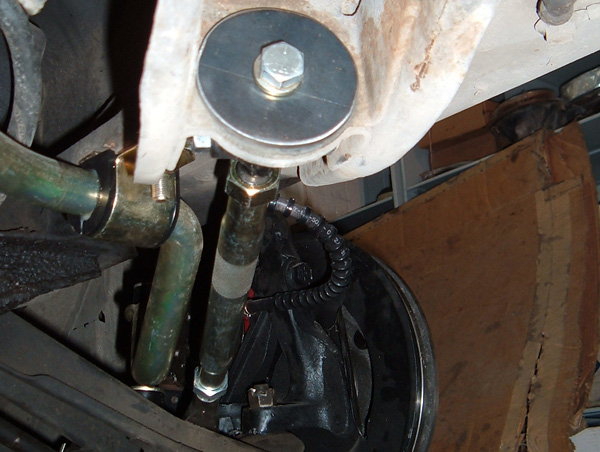
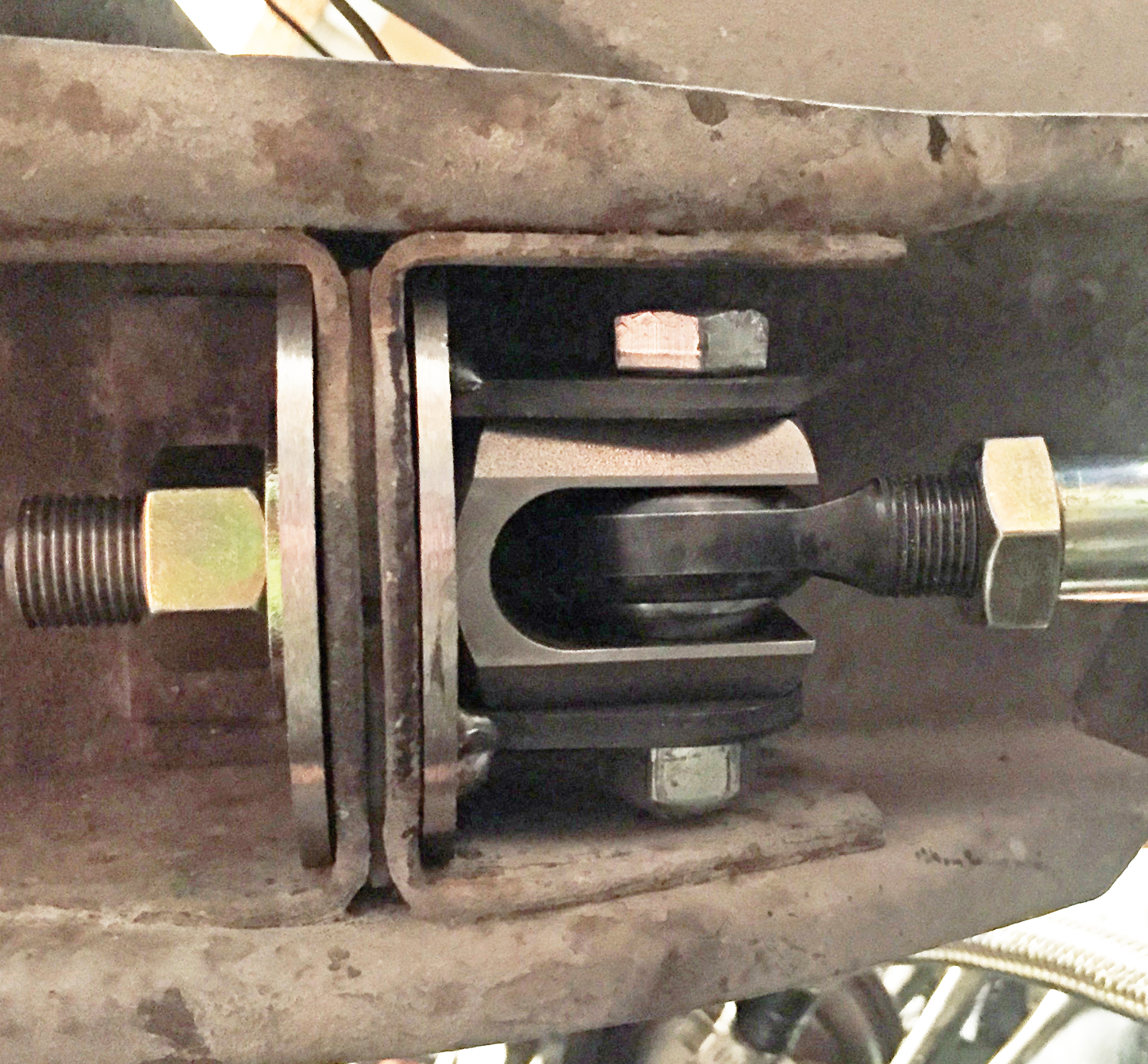
Clevis assembly mounted in the car to the mounting plate. Notice
the tight clearance between the assembly and mounting rails.
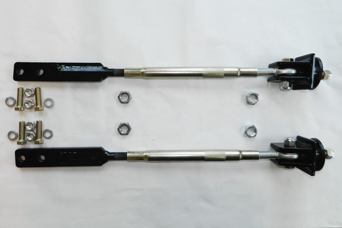
Here we have it, a completed adjustable strut rod in my car. All
the car needs now is a high quality performance alignment.
Other Things To Consider:
Concerns have been expressed that a 7/16” bolt is insufficient to deal
with the stress and pressure that this application will subject it to,
especially since the aftermarket uses 1/2” mounting hardware. My
response to this is simple: force applied to the bolt is in
compression and tension, not side to side shearing force. The
free movement of the heim joint eliminates any shearing force that
would be applied to the 7/16” bolt. Secondly, a 1/2” fine thread
bolt and a 7/16” fine thread bolt have the same number of teeth per
inch at the same tooth depth. That means that the only decrease
in holding power is related to the loss in surface per tooth area, due
to a 7/16” bolt having a smaller diameter than a 1/2” bolt. The
number of threads in the clevis compensates for the difference in
area. On aftermarket systems, they use a 1/2” bolt and everything
is held in place with a single 1/2” retaining nut. A 1/2” nut has
8 threads inside it where as the clevis has 12. If you do the
math, the square area of a 7/16” circle is .151”. The square area
of a 1/2” circle is .197". If you multiply that area times the
number of teeth, you get 1.812” for the 7/16” bolt threaded into the 12
threads of the clevis, as opposed to only 1.574” for the 1/2” bolt
threaded into the 8 threads of a 1/2” nut. As you can see, with
more teeth being used in the clevis, and thus more surface area, the
7/16” bolt has 15% more holding power than a 1/2” bolt with just a
nut. Lastly, the clevis comes from the factory with a 4250-pound
rating and that rating is going to include the 7/16” mounting hole, as
long as high quality hardware is used in it.
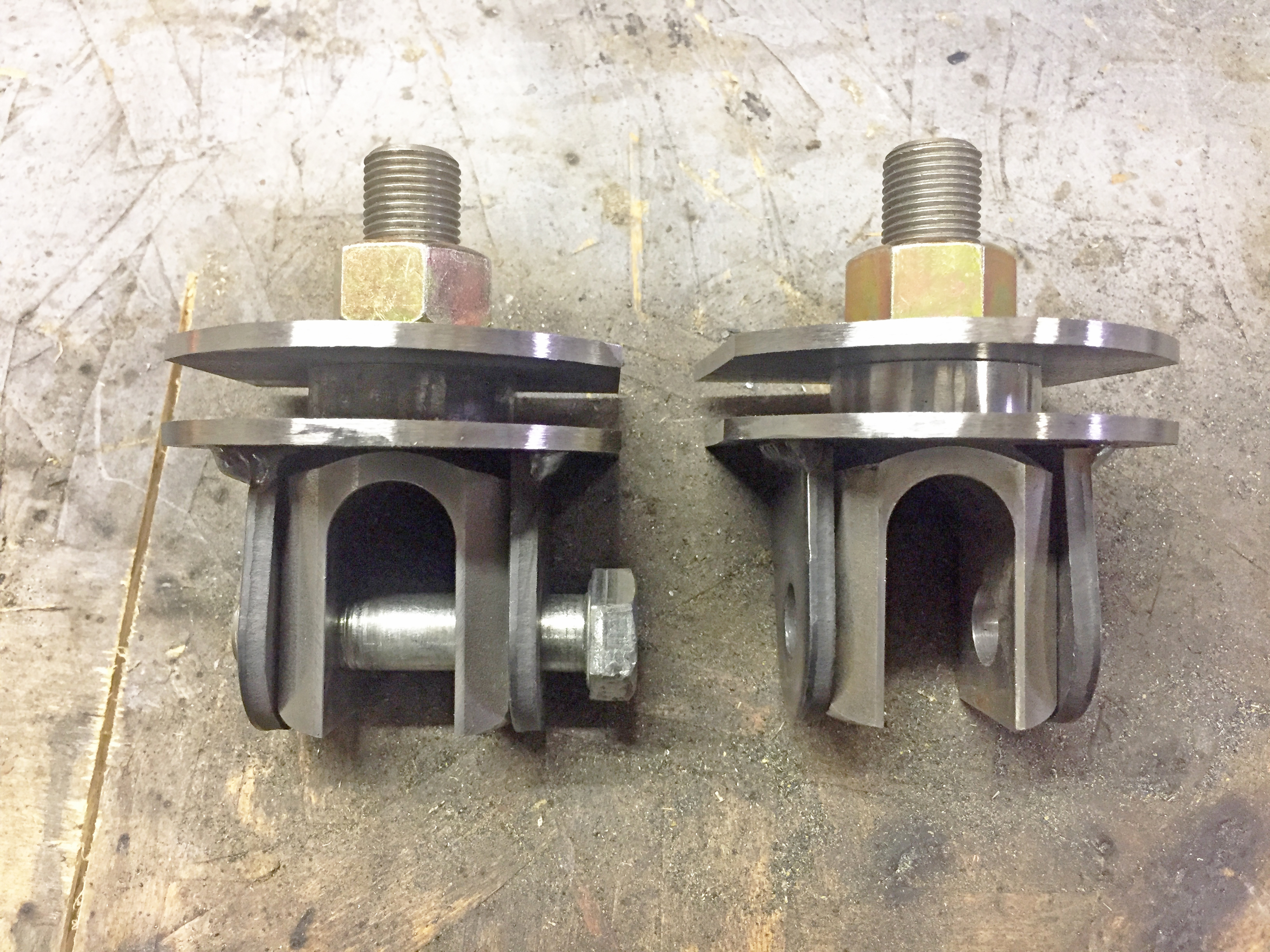
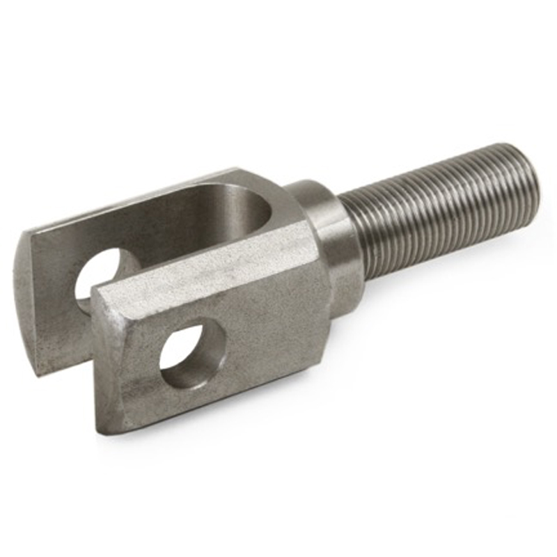
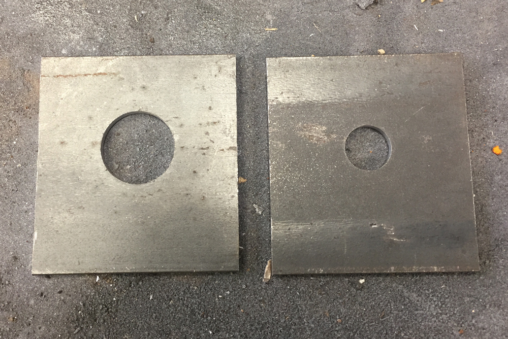
Building a Replacement Mount Using a Steel Clevis:
As
I mentioned above there have been some issues finding the rod end I
used and there has been some question as to whether the rod end was
cast iron or cast steel. To that end I have found a replacement
part. The part I used is pictured below and here is a link on where to get them.
Below that are some pictures and description of the fabrication work I
did to make them into a replacement mount for my adjustable strut
rods.
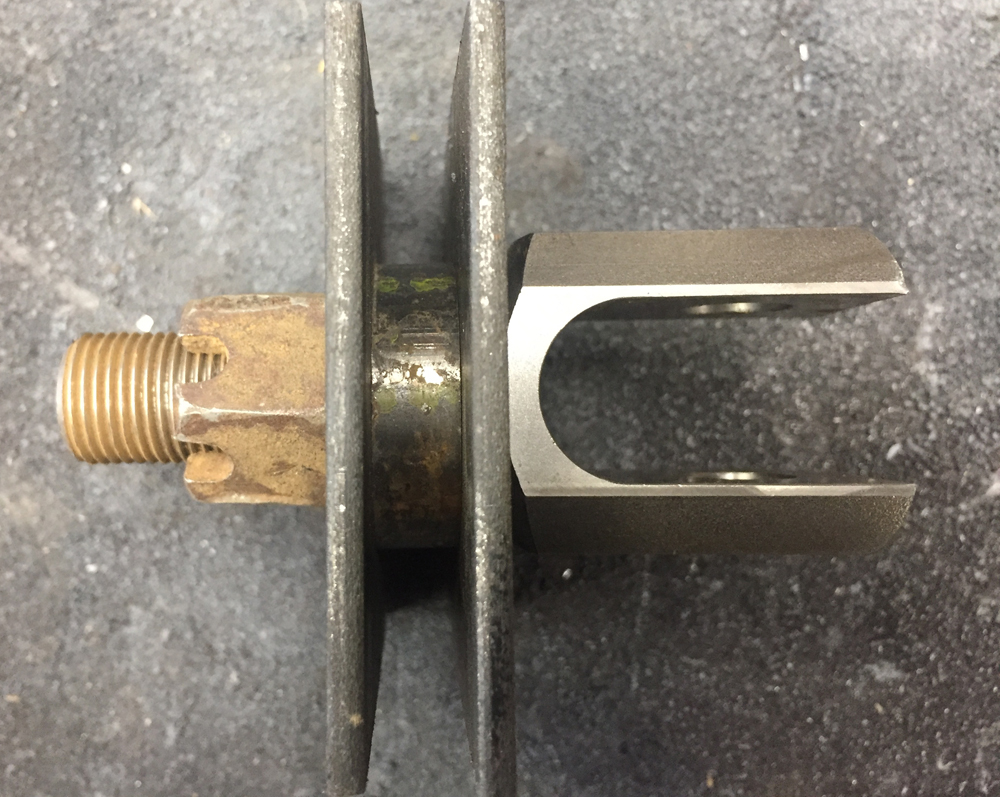
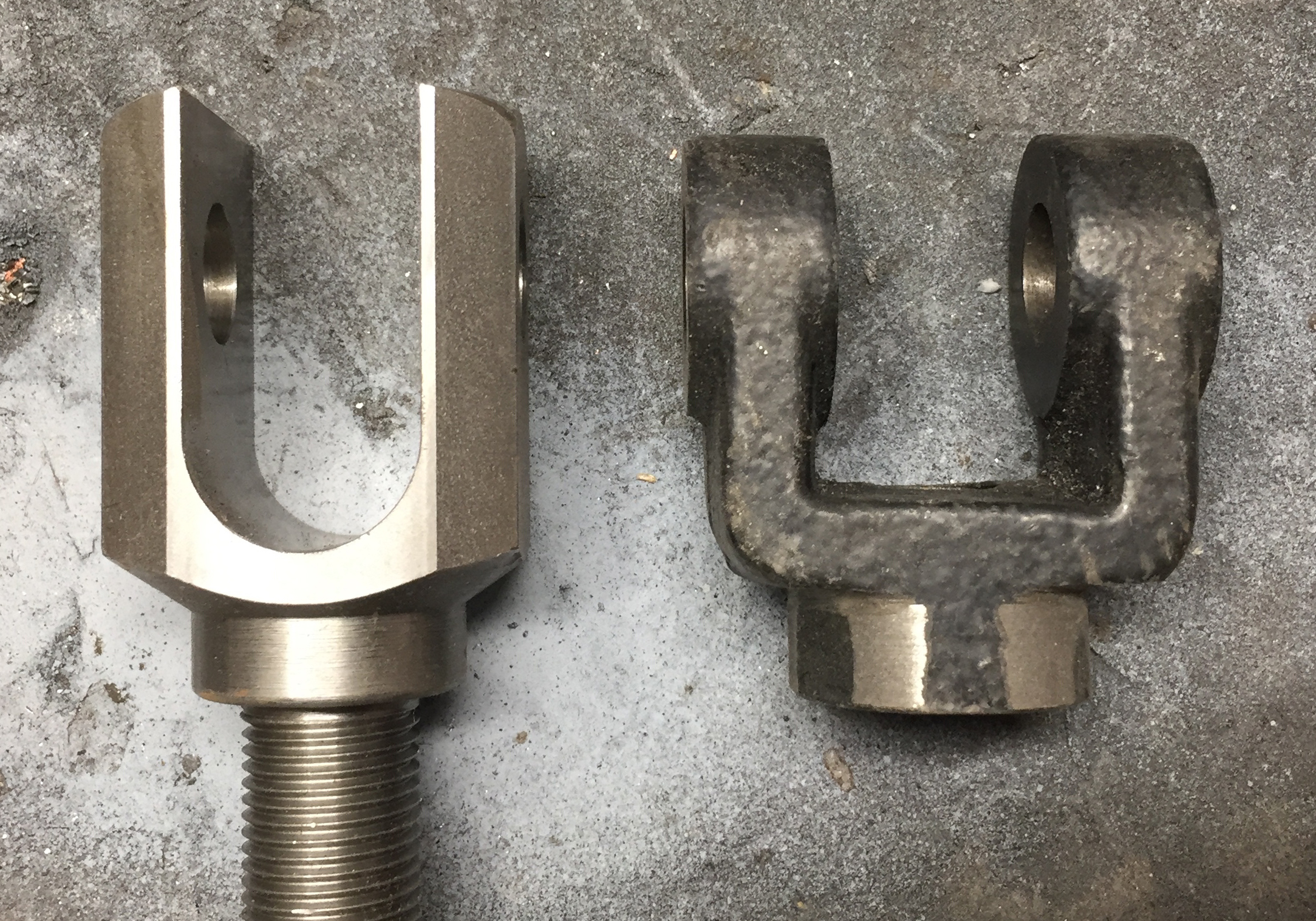
Comparison Between the Steel Clevis and the Cast Rod End
I
started by cutting two pieces of steel to be a snug fit in the strut
rod pocket. I then drilled a 1” hole in one and a 5/8” hole in
the other.
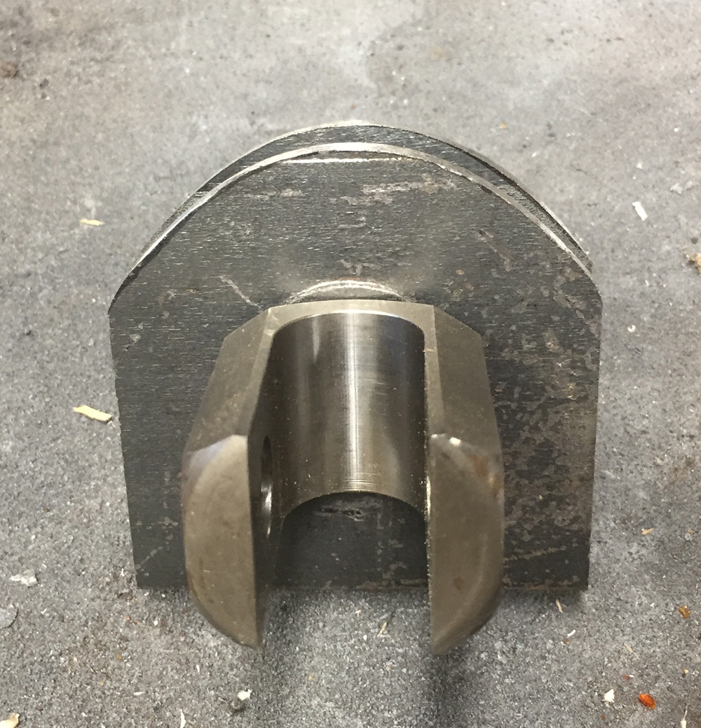
This allowed me to use the plates to position the clevis and then I was able to use the pipe spacer.
I then rounded out the bottom of the brackets to match the rounded underside of the pocket.
The
next step was to address welding some tabs on both sides of the clevis.
The tabs will be welded to the main plate for extra strength but
the clevis will still be removable. NOTE: I did not do any welding to the actual steel clevis as I did not want mess with its structural integratity. I used some weld on tabs left over from a previous project that I cut for this application and welded into place.
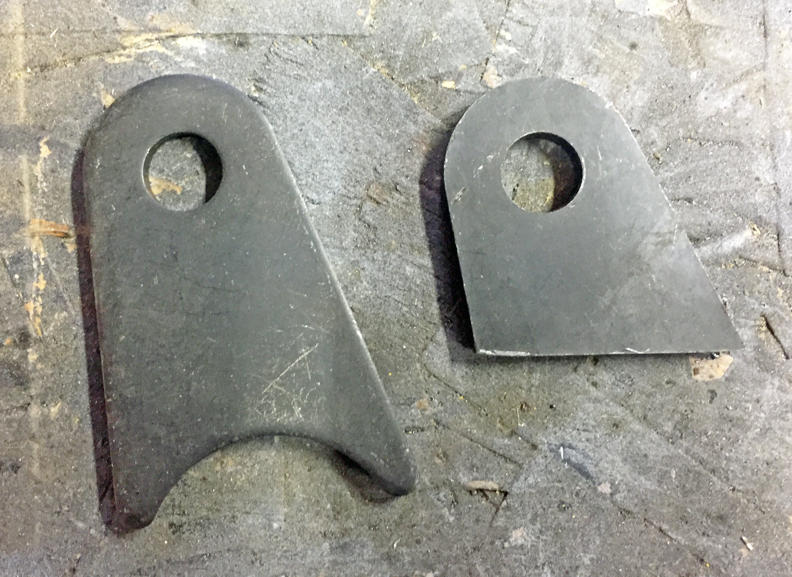
I
am currently still using the pipe spacer but I may yet machine some
spacers to take up the slack. (I.D. of the pipe is larger than the
sholder on the steel clevis) At this point I don’t know how
necessary a tighter fitting spacer is with the way I designed the
bracket to fully fill the pocket.
Here we have the mount in the car attached to the heim joint and strut rod.
For those of you who would rather buy than fabricate :
Rosehill Performance Parts sells high quality adjustable strut rods at
a much lower price than the other aftermarket options.
They are available for years 1964&1/2-1966 and 1968-1970.
These are quality race proven units and they utilize high quality 5/8"
heim joints. They mount directly to the vehicle with solid
professionally fabricated mounting brackets. Purchasing information for
these strut rods can be found at this web page http://www.rosehillperformanceparts.com
Disclaimer on Daze Tech Tips
I
am not an expert in this field. I have performed these modifications
myself with very good results. I am passing along restoration and
performance tips for the purpose of education. If you are
concerned about reliability or safety issues, I do not recommend that
you or any other individual perform these changes or attempt to modify
your cars from stock configuration except under your own
volition. I do not assume nor accept any liability for the use of
this information or how it is applied.