 |

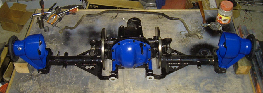
"The project so far has been fun but relatively simple and unchallenging, however, that is all about to change as we are now venturing into the heart of the IRS project, narrowing of the half shafts, narrowing the LCAs, and changing the bolt pattern on the wheel flanges."
Getting
the correct track width:
As with most aspects of this project, there are several schools of thought on making an IRS unit fit in your application. One option is to use the Jaguar unit as it was designed and then run wheels with extreme back spacing. The idea is that the width of the rear end plus the minimal offset of the wheels will be similar in width to a standard rear end assembly with normal backspacing and off set. In theory, this is a good idea, however, by requiring wheels with extreme back spacing, your wheel choices are greatly reduced. Also, the hub on an IRS unit takes up quite a bit of space and some wheels with extreme backspacing may end up hitting the hub. Another thing to consider in the case of a Mustang install, is that the nearly 4” difference in track width, between an early Mustang rear end and XJ Jaguar assembly, may not be completely compensated for by large backspacing wheels, and modifications to fenders may still be required to make the assembly fit. For these reasons, I chose to narrow my Jaguar unit for a correct fit. When narrowing any rear end, whether it is a live axle or IRS, you need to consider what you have planned for the car with special attention paid to wheel and tire widths. Some wheel and tire combinations, such as modern Mustang rims, may require a slightly wider rear end. The stock 65-66 Mustang rear end measures 58” hub to hub, so a target width of that, plus or minus an inch, should be your goal depending on your plans and application. NOTE normally you measure a Ford live axle rear end housing minus the brakes from housing flange to housing flange, and such a measurement on a 65-66 Mustang would be 52.25”. For this project, I measured from the outside of the hub instead because there is no other place to get a measurement that translates on the IRS unit. The width of an XJ6 or XJ12 IRS unit is 61.75”, wheel flange to wheel flange, so to maintain the 58” width of a 64.5-66 Mustang, 1.875” needs to be removed from each side. In the case of my application, I chose to remove 2.125” from each side for a final width of 57.5” hub to hub. I chose this for two reasons, first, I wanted a little extra clearance for my tires, and two, the half shafts start at 16.125” u-joint center to u-joint center and having them shortened to an even 14” just seemed to make sense somehow. Narrowing the half shafts: On the Jaguar IRS system, the half shafts serve triple duty. They provide the connection between the differential and the wheels to drive said wheels, they act as upper control arms keeping the hubs vertical during suspension travel, and their connection to the differential provides a means of adjusting camber. With so many functions, these parts are very important and the utmost care needs to be taken in narrowing them. I am a competent fabricator, however, the greater part of what makes me “competent” is knowing when the task that lies before me is beyond my skill set. Narrowing half shafts is one of those tasks that, for all but a select few with the correct skill set and access to the correct equipment, should be farmed out to a driveline shop. NOTE if a half shaft were to fail while in use, the results could be catastrophic, so weigh the potential consequences and think very carefully before attempting to narrow the half shafts yourself. If the Jaguar half shafts were like a typical driveline made from a piece of mechanical tubing with a yoke pressed in and welded to each end, then there would only be one option for narrowing them. However, when Spicer originally designed and manufactured the half shafts for the Jaguar, they decided on solid forged steel pieces, much like the axles on a live axle system. This creates challenges in narrowing them, however, it also allows for more than one option on how to do it. Even though, in most cases, the work will be done by someone else, you, as the consumer, have three choices as to how you end up with the correct half shaft length: “Bevel and weld”, “Turn down, cut, press & weld”, “Fabricate from scratch”, and with the aid of your machinist a decision can be made as to which is the best option for your application and financial resources.
Fabricate
from scratch:
Another
option is to have custom half shafts made from new yokes or used
drivelines. The yoke on the Jaguar half shafts is sized for a
standard Chevy u-joint so new yokes can be used or used Chevy drive
lines can be cut down to fit between the differential and the
hub. The advantage to this is a solid quality piece in many
cases
made from all new components. The down side is using drive
line
yokes will make the shafts wider than the original half shafts, which
my require spacing out the coil over shocks so that there is clearance
between the springs and half shafts. Also, finding used Chevy
drive lines that are around 2” or less may be difficult and
when I
looked into ordering new yoke ends, it was going to cost me over
$100.00 a piece just for the yokes, not including the machine
work. That is the main reason why I chose to have the
original
half shafts used to make the yokes.
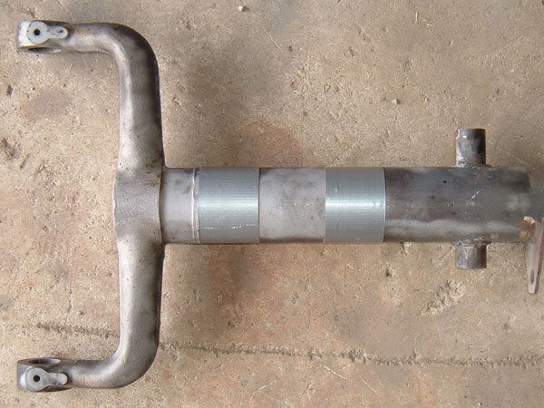
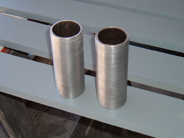
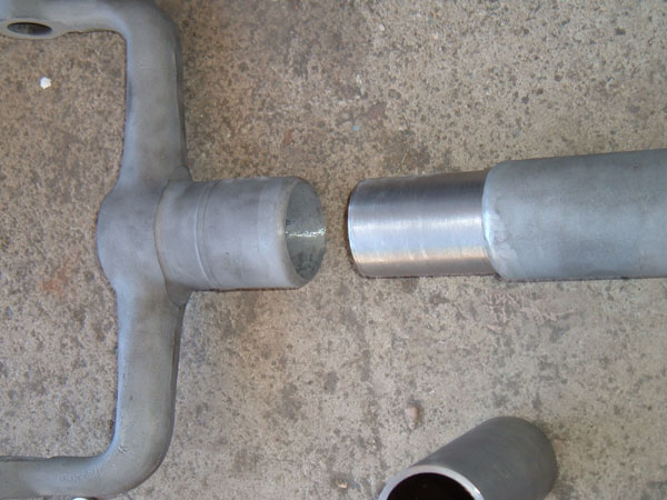
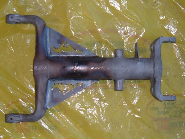
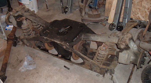
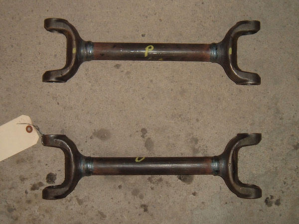 This is what my
shafts looked like after they were narrowed at a local driveline shop.
After this picture was taken, they were sand-blasted and powder coated. Narrowing the LCAs: Narrowing the LCAs
is easier than the
half shafts in that it can be done at home but don’t let the
DIY aspect
of the process overshadow the importance of narrowing them
correctly. Half of the rear end weight will be on each of
these
half shafts and making sure they are narrowed properly is
critical. Paying attention to the details and knowing the
limitations of your skill set will ensure this process is completed
correctly.
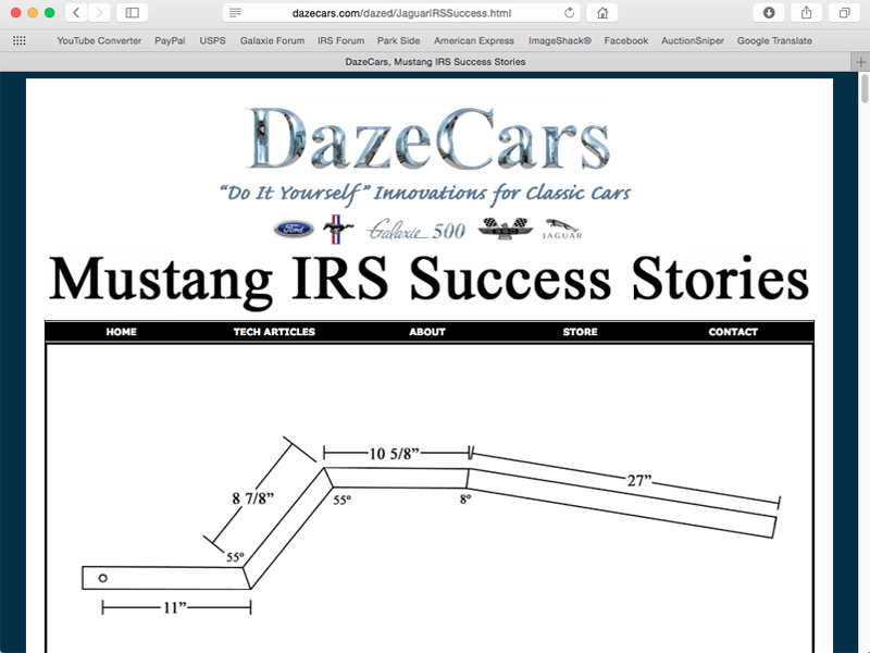
Taking measurements and making indexing marks: The first thing
that needs to happen in
the process is to take a whole bunch of measurements so that you know
exactly what the LCAs looked like prior to modifying them. YOU MUST do
this step because, if you do not, you will not have any frame of
reference as to how long things need to be. Once you think you have
taken enough measurements, take a few more. Not only take
measurements and notate them but also notate where the measurements
were taken from so you can measure for the exact same points when
measuring the mocked up pieces after material has been
removed.
Another wonderful point of reference is to make indexing marks on the
side of the tubing so that when you put it all back together you can
check to see that the lines are lined up and know that everything is
being put back together correctly. To make lines, place a
piece
of angle iron on the LCA tubing and score a line along the side of the
angle iron on the tube. I only did 1 indexing line per
LCA.
Make sure the line is longer than the section of material to be removed
so that it will be on both halves after the material is removed.
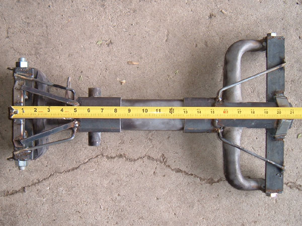
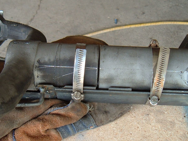
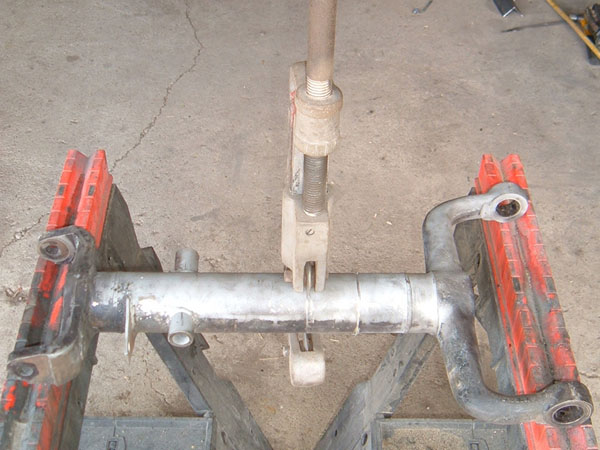
Cutting the LCAs: In order to narrow
up the LCAs, you will
need to cut out a section of the tubing. The professional way
to
do this is put the LCA in a lathe and use the lathe to cut
it.
This takes a large lathe and probably the services of a machine
shop. In the pursuit of maintaining a DIY project, I devised
a
way to do it at home. I started by setting both LCAs side by
side
and made a mark on the differential end of each LCA where the cut would
be, so that the cuts would be the same on both LCAs. I then placed tape
around the tube so that I had a nice straight line to follow, and then
measured the distance I wanted to remove and applied a second piece of
tape at that measured distance. Using the edge of the tape, and being
careful not to damage it, I took a triangular file and made a small
grove along the edge of the two pieces of tape. This gave me
two
groves 2.25” apart. I know you are thinking the
half shafts were
only narrowed 2.125” and we will discuss the discrepancy
later in this
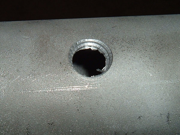
article. I was then able to use a large 3-blade pipe cutter
to
cut out the 2.25” section. The reason I cut the
groves with a
file first is I have found that it is easier to use a large pipe cutter
and get an accurate cut if there is already a groove for the blades to
rest in.
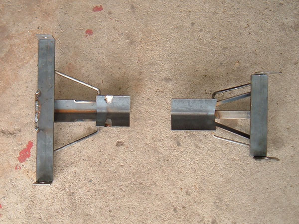
Getting the pieces indexed and measured for welding: Prior to welding
the halves together,
the jig will need to be installed, measurements will need to be taken
on both the arm and the jig to ensure the correct length and the
indexing marks need to be checked. It is also a good idea to
lay
the parts out on a flat surface and make sure that the distances
between the eyes of the LCA and the flat surface are the
same.
This will ensure that both ends of the LCA are correctly
indexed.
I measured mine by making sure the hub end was shimmed so that the
centers were the same distance to the surface and then measured the
distance between the machined surface and the table on the differential
end. I shimmed the hub end and measured the differential end
because the wider differential end will show greater differences than
the hub end, due to the extra width. When I measured mine,
the
jig only allowed a.02” difference, which probably would have
been fine
but I couldn’t let it go and adjusted it by loosening the
clamp on the
differential end, tapped the arm lightly with a hammer, measured again
and, once the measurements were identical, tightened the clamp back
up. With everything held in place, the half shafts are ready
to
be welded.
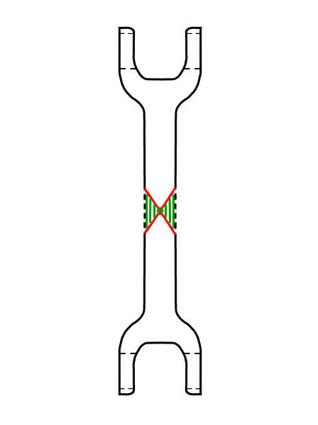
Welding the pieces together: As
with the half
shafts, there are
several schools of thought, and thus, different options on how to best
accomplish the task of joining the two halves back together.
Prior to narrowing my LCAs, as with the half shafts, I did
much
research and came up with three techniques/options for welding things
back together : “Bevel & butt
weld”, “Sleeve” and
“Gusset”.
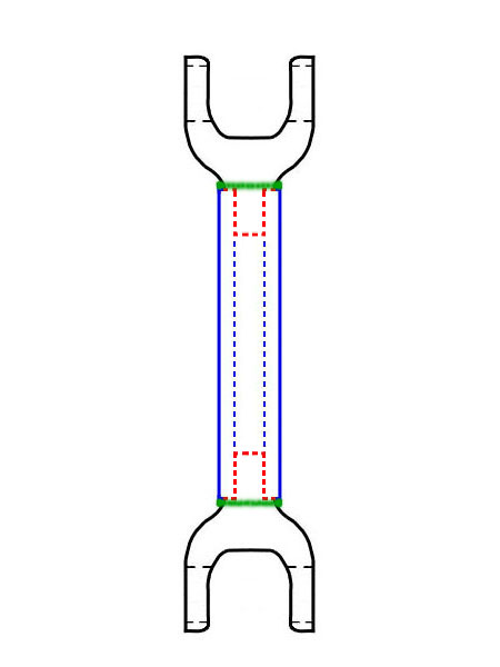
Sleeve: An improved option
over the butt weld
option is to also sleeve it and then butt weld. By cleaning
up
the inside of the tubes, you can machine a tube to fit inside and help
line things up. This will keep the tubing straight and add
quite
a bit more strength. This also allows for plug weld holes to
be
drilled through the LCA tubing on the arms so that more than just the
butt weld can hold the sleeve to the arm and gives you another place to
make tack welds.
Gusset: Yet
another improved option over the
butt weld technique is to also install gussets after butt welding the
two halves together. The gussets will overlap both the
original
butt weld joint and the new butt weld joint on each side and provide
another way to connect the two pieces together. Also, this
improves rigidity of the LCA and completely eliminates any LCA
flex.
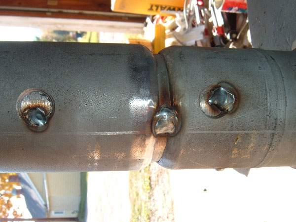
 The way I see it is if I am going to have gussets, I might as well make them look good!! Not being one to
do things in a less
then over built way, I chose to use both sleeves and gussets. Adding
the gussets not only added strength but also afforded me the
opportunity to have some really cool lightening holes cut
out.
When I put these together, I tack welded the two halves of the LCA
together and then took them into a professional welder to be welded up,
including the installation of the gussets. NOTE as
I said
before I am a competent fabricator, however, the greater part of what
makes me “competent” is knowing when the task that
lies before me is
beyond my skill set. Could I weld up the LCAs, yes, would
they be
strong enough, probably, but why run the risk of not having
professional quality welds when it would not be that expensive or time
consuming for me to take the tack welded arms to a certified welder and
have them finished up.
Changing the bolt pattern: When
it comes to
wheel bolt pattern, if
you are trying to put a Jaguar IRS in a classic Chevy, you have it made
because the Jaguar bolt pattern is the same as a classic Chevy, 5 on
4.75”, but if you want to put one of these units in a classic
Ford, the
bolt pattern is different, Ford uses a 5 on 4.5”
pattern. As with
other aspects of this project, there are several options in dealing
with this issue. The first is to run different pattern wheels
on
the back than on the front. Problem with this is that you
need to
carry two spare tires. The second option is to use hub
adaptors
that change the bolt pattern. This option is not ideal
because
bolt pattern adaptors are .75” to 1” thick and, if
you are planning on
this option, the unit will need to be narrowed even further.
Also, adaptors like this sell for around $50.00 a pair.
Another
option is to buy the correct bolt pattern wheel flanges from places
like CWI. They sell hubs that have been modified and have the
correct bolt pattern machined into them. This option gives
you a
quality flange with the correct pattern but has the down side of being
fairly expensive.
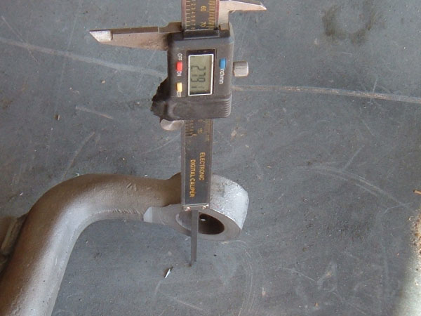
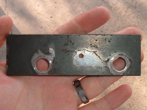
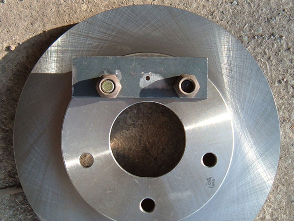
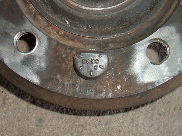
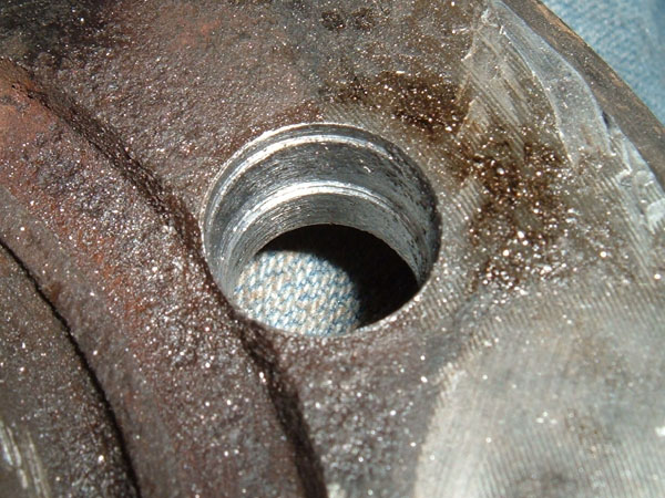
I didn’t really like any of these options and, there again, was striving for this to be as much of a DIY project as possible, so I decided to drill out the pattern myself. When I first suggested to some other car enthusiasts that I was planning to drill the pattern myself, I was told not to drill the pattern because it would be almost impossible to have all 5 holes be in the correct spot. I pondered the issue and, at first, thought about making a 10-hole jig. (5 holes each pattern) Problem is, I still would have a hard time getting all 10 holes in the correct position. One day while contemplating this issue, I had an epiphany, instead of making a 10-hole jig, make a 3-hole jig and rotate it from position to position. I made the jig (Homemade Tool # 4) by drawing 2 circles, a 4.75” circle with a 4.5” circle inside it. I then measured the distance between two studs on the Jaguar wheel flange and plotted those 2 points on the outer circle. Using these two plotted points I measured between them and plotted a center point on the inner circle. The drawing was then transferred to a piece of steel and the three holes were drilled out, .5” inches on the outer ones and .125” for the center hole. The jig can now be bolted to the flange and a pilot hole drilled. The beauty of this jig is that even if the pilot hole is not perfectly centered, as long it is on the 4.5” circle, it will be in the same location between the two studs on all 5 holes, giving a perfect star pattern. After creating the jig, I purchased a cheap Chevy rotor and drilled out the Ford pattern to ensure that the jig was accurate prior to drilling the hub. 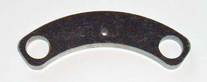 If you would like to purchase a CNC cut 3-hole bolt pattern Jig rather than make your own I now offer them for sale. To purchase one click here Finding wheel studs: Before you can drill your wheel flanges, you need to purchase your wheel studs so you know what size to drill the holes. Finding the correct press fit wheel studs can be a challenge, due to the fact that moving the holes in 1⁄4” moves them very close to the machined surface on the backside of the wheel flange. With that in mind, the new press stud holes need to be no bigger than 17/32”. Most 1⁄2” wheel studs have 9/16” – 5/8” Knurl Diameters and so would be too big for the application. To come up with the correct stud, I went to my local tire and wheel supplier with my digital calipers in hand and asked to look through their wheel stud selection. I found a stud that has a Knurl Diameter 0.558, which makes it a perfect press fit in a 17/32” hole so I purchased 10 of these for my project. At the time, I was not able to cross-reference the part numbers I had for the studs to find out what they were normally used for. Some time later, I went back to get 10 more for another Jaguar assembly I have that is going in my 62 Galaxie and could not find the same studs so I found another stud that would work. The new one has a Knurl Diameter of 0.536 making it an ideal press fit for a .5” hole. Not being able to find the original stud concerned me, in case I ever needed to replace one, so I once again began a search for what application either of these studs were designed for. This time I was successful and the first set of studs I purchased are Dorman part #98141 used on the 1980-1983 Ford F-100. The second set of studs I purchased are Dorman part #610258 used on 1998 Jaguar XJ8 and the 1967-1978 Cadillac.
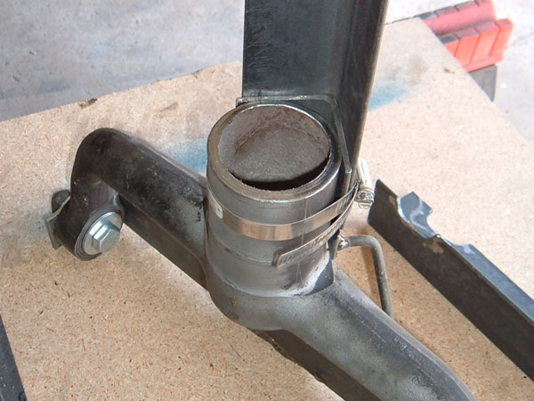
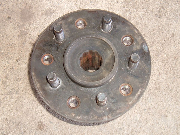
Once I had my jig built and I had my wheel studs so that I knew what size to drill my holes, I was ready to modify the Jaguar wheel flanges. To do this, I removed the original Jaguar wheel studs by grinding of the back crimped edge of the wheel studs and unscrewed them. I had to install old lug nuts onto the studs and weld the nuts to the studs in order to use a breaker bar to bust them loose. The threaded holes left by the wheel studs were ideal to bolt the jig into place. With the jig bolted in, I drilled a pilot hole and then positioned it on the next two studs, making sure the same side of the jig always stayed up. I drilled the pilot holes one bit size at a time up to .5” all the way through and then 17/32” halfway through from the backside to accommodate the .558 Knurl Diameter of the new studs. Prior to using them I modified the press studs by trimming of one edge so that there was proper clearance between the studs head and the hub housing. I then pressed the studs into place. This gave me wheel flanges with the correct Ford bolt pattern.
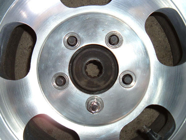 The hub is a perfect fit in this 5 on 4.5 bolt pattern rim With everything modified for the purpose of narrowing the unit and the correct bolt pattern drilled, this project can now go into the assembly phase. In the next article, page IV, we will look at the differential rebuild, drive shaft rebuild, and the rebuilding of the hubs.
|